Web Analytics
sales@aipcba.com
DE
Lieferung elektronischer Komponenten > Schnittstellen-ICs > TI >

PCA9515ADRGR Bestand und Preise

TI IC Logic Repeater 2.5V/3.3V 8Pin WSON EP T/R
1.24
PCA9515ADRGR
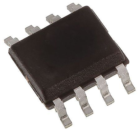
Das gezeigte Bild ist nur eine Darstellung. Genaue Spezifikationen sind dem Produktdatenblatt zu entnehmen.
PCA9515ADRGR TI
TI
  • Hersteller:
    TI
  • Hersteller-Nr:
    PCA9515ADRGR
  • AiPCBA-Teilenummer:
    CM23104308
  • Preis (EUR):
    1.24
  • AiPCBA-Lager:
    9,108 Stk
  • Verfügbarkeit:
    7,179 Stück auf Lager
    Lagerbestand des Lieferanten, muss mit dem Verkauf bestätigt werden
  • Produktkategorie:
    Schnittstellen-ICs
  • Produktbeschreibung:
    IC Logic Repeater 2.5V/3.3V 8Pin WSON EP T/R
  • Dokumentation: 3D-Modell
PCA9515ADRGR Kaufen PCA9515ADRGR Bestand & Preis aktualisiert um 2024-08-10 03:50:22
  • Aktualisieren
    Teilenummer: PCA9515ADRGR
    AiPCBA P/N: CM23104308
    Hersteller: TI
    Paket: WFDFN-8
    Preis
    1.24
    Gesamt: 16,287 Stk
    MOQ: 1
    Versand von: Lagerhaus Hongkong
    Versanddatum: 2024/08/15 (erwartet)
  • Kaufen
    • *Mengenangebot anfordern?
    • *Bestand ändert sich sehr schnell
    • Kontakt sofort!
    *Aufgrund des Lagerbestands bitte weiter schwanken Kontakt für den neusten Preis und Lagerbestand.

    Teilebestand prüfen

    Bestandsprüfung
    108.116 Teile im AiPCBA-Lager gelagert
    Erinnerungen zur Betrugsprävention
    Kürzlich haben wir festgestellt, dass Kriminelle vorgaben, AiPCBA zu sein, um zu betrügen oder zu versuchen, Fälschungen zu verkaufen ausgefallene Komponenten zu günstigen Preisen.
    AiPCBA hat ein Komponentenprüflabor im Jahr 2021 mit dem Ziel, qualitätsgesicherte Komponenten bereitzustellen.
    Wir empfehlen unseren Kunden dringend, sich für zuverlässige Komponentenlieferanten zu entscheiden.
    Bitte beachten Sie, dass die einzigen offiziellen Website- und E-Mail-Suffixe sind aipcba.com
    PCA9515ADRGR Spezifikationen Ähnliche Produkte anzeigen (99+)
    TYP
    BESCHREIBUNG
    AUSWÄHLEN
    Hersteller
    TI
    Kategorie
    Schnittstellen-ICs
    3D-Modell
     3D-Modell
    Montagesmethoden
    Surface Mount
    Anzahl von Pins
    8 Pin
    Verpackung
    WFDFN-8
    Netzspannung
    2.30V ~ 5.50V
    Ausgang-Schnittstellen
    2 Output
    Versorgungsstrom
    500 µA
    Anzahl der Kanäle
    1 Channel
    Input-Kapazität
    7 pF
    Betriebstemperatur (max.)
    85 ℃
    Betriebstemperatur (Min)
    -40 ℃
    Versorgungsspannung
    2.3V ~ 3.6V
    Ähnliche Produkte anzeigen
    PCA9515ADRGR Datenblatt-PDF
    PCA9515ADRGR Datenblatt PDF
    24 Pages, 1312 KB
    2015/03/27
    Ansicht
    PCA9515ADRGR Datenblatt PDF
    22 Pages, 1045 KB
    2014/06/14
    Ansicht
    PCA9515ADRGR Datenblatt PDF
    18 Pages, 598 KB
    2012/03/28
    Ansicht
    PCA9515ADRGR Datenblatt PDF
    22 Pages, 1047 KB
    2014/07/28
    Ansicht
    PCA9515ADRGR Datenblatt PDF
    19 Pages, 108 KB
    2009/04/06
    Ansicht
    PCA9515ADRGR Datenblatt PDF
    16 Pages, 95 KB
    2009/04/09
    Ansicht
    PCA9515ADRGR Datenblatt PDF
    24 Pages, 1312 KB
    Ansicht
    PCA9515ADRGR Anderes Datenblatt
    22 Pages, 1009 KB
    Ansicht
    PCA9515ADRGR Anderes Datenblatt
    8 Pages, 489 KB
    2014/06/25
    Ansicht
    PCA9515ADRGR Andere Referenzen
    1 Pages, 145 KB
    2011/06/15
    Ansicht
    Größe & Paket
    TYP
    BESCHREIBUNG
    Betriebstemperatur
    -40℃ ~ 85℃
    Produktlebenszyklus
    Active
    Verpackungsmethoden
    Tape & Reel (TR)
    Umwelt
    TYP
    BESCHREIBUNG
    RoHS-Standard
    RoHS Compliant
    Bleifreier Status
    Lead Free
    Exportklassifikationen
    TYP
    BESCHREIBUNG
    ECCN Code
    EAR99
    Funktionsübersicht
    • This dual bidirectional I2C buffer is operational at 2.3-V to 3.6-V VCC.
    • The PCA9515A is a BiCMOS integrated circuit intended for I2C bus and SMBus systems applications. The device contains two identical bidirectional open-drain buffer circuits that enable I2C and similar bus systems to be extended without degradation of system performance.
    • The PCA9515A buffers both the serial data (SDA) and serial clock (SCL) signals on the I2C bus, while retaining all the operating modes and features of the I2C system. This enables two buses of 400-pF bus capacitance to be connected in an I2C application.
    • The I2C bus capacitance limit of 400 pF restricts the number of devices and bus length. Using the PCA9515A enables the system designer to isolate two halves of a bus, accommodating more I2C devices or longer trace lengths.
    • The PCA9515A has an active-high enable (EN) input with an internal pullup, which allows the user to select when the repeater is active. This can be used to isolate a badly behaved slave on power-up reset. It never should change state during an I2C operation, because disabling during a bus operation hangs the bus, and enabling part way through a bus cycle could confuse the I2C parts being enabled. The EN input should change state only when the global bus and the repeater port are in an idle state, to prevent system failures.
    • The PCA9515A also can be used to run two buses: one at 5-V interface levels and the other at 3.3-V interface levels, or one at 400-kHz operating frequency and the other at 100-kHz operating frequency. If the two buses are operating at different frequencies, the 100-kHz bus must be isolated when the 400-kHz operation of the other bus is required. If the master is running at 400 kHz, the maximum system operating frequency may be less than 400 kHz, because of the delays that are added by the repeater.
    • The PCA9515A does not support clock stretching across the repeater.
    • The output low levels for each internal buffer are approximately 0.5 V, but the input voltage of each internal buffer must be 70 mV or more below the output low level, when the output internally is driven low. This prevents a lockup condition from occurring when the input low condition is released.
    • Two or more PCA9515A devices cannot be used in series. The PCA9515A design does not allow this configuration. Because there is no direction pin, slightly different valid low-voltage levels are used to avoid lockup conditions between the input and the output of each repeater. A valid low applied at the input of a PCA9515A is propagated as a buffered low with a slightly higher value on the enabled outputs. When this buffered low is applied to another PCA9515A-type device in series, the second device does not recognize it as a valid low and does not propagate it as a buffered low again.
    • The device contains a power-up control circuit that sets an internal latch to prevent the output circuits from becoming active until VCC is at a valid level (VCC = 2.3 V).
    • As with the standard I2C system, pullup resistors are required to provide the logic high levels on the buffered bus. The PCA9515A has standard open-collector configuration of the I2C bus. The size of these pullup resistors depends on the system, but each side of the repeater must have a pullup resistor. The device is designed to work with Standard Mode and Fast Mode I2C devices in addition to SMBus devices. Standard Mode I2C devices only specify 3 mA in a generic I2C system where Standard Mode devices and multiple masters are possible. Under certain conditions, high termination currents can be used.

    AiPCBA-Zertifizierungen

    AiPCBA verspricht die Produktqualität und -sicherheit mit ISO 9001, ISO 13485, ISO 45001, UL-, RoHS-, CQC- und REACH-Zertifizierungen
    Prüfen Sie unsere Zertifizierungen >
    Bestelldetails & relevante Informationen
    •  Die hier aufgeführten Geschäftsbedingungen dienen nur als Referenz, die tatsächlichen AGB unterliegen dem Angebot des Verkäufers.
      - Bitte bestätigen Sie die Spezifikationen der Produkte bei der Bestellung.
      - MOQ bedeutet die Mindestbestellmenge, die erforderlich ist, um jedes Teil zu kaufen.
      - Wenn Sie spezielle Bestellanweisungen haben, vermerken Sie diese bitte auf der Bestellseite.
      - Die Pre-Shipment Inspection (PSI) wird angewendet.
      - Sie können uns jederzeit eine E-Mail senden, um den Bestellstatus zu überprüfen.
      - Bestellungen können nach Versand der Pakete nicht mehr storniert werden.
    • - TT im Voraus (Banküberweisung), PayPal kann ausgewählt werden.
      - Nur Barüberweisung. (Überweisungen mit Schecks und Wechseln werden nicht akzeptiert.)
      - Der Kunde ist für die Zahlung aller möglichen Gebühren verantwortlich, einschließlich Umsatzsteuer, Mehrwertsteuer und Zollgebühren usw.
      - Wenn Sie die detaillierte Rechnung oder Steuernummer benötigen, senden Sie uns bitte eine E-Mail.
    • - FedEx, DHL und UPS können ausgewählt werden.
      - Sie können auswählen, ob die Versandkosten von Ihrem Versandkonto oder von unserer Seite berechnet werden sollen.
      - Bitte bestätigen Sie dies im Voraus mit dem Logistikunternehmen, wenn Sie sich in einem abgelegenen Gebiet befinden.
      (Es können zusätzliche Gebühren (35-50 USD) für die Lieferung in diese Gebiete anfallen.)
      - Lieferdatum: normalerweise 2 bis 7 Werktage.
      - Tracking-Nummer wird gesendet, sobald Ihre Bestellung versandt wurde.
    • - Sorgfältig geprüft und verpackt von AiPCBA
      - Vakuumverpackung
      - Antistatische Verpackung
      - Antivibrationsschaum
    • - Einkommensqualitätskontrolle (IQC), über 800 qualifizierte Vertriebspartner.
      - 500 m² Labor für fortschrittliche Komponententests, Fälschungserkennung, RoHS-konform usw.
      - 2000 m² digitales Komponentenlager, konstante Temperatur und Luftfeuchtigkeit
      - Entkapselungsinspektion
      - Röntgeninspektion
      - XRF-Inspektion
      - Elektrische Prüfung
      - Oberflächenprüfung
    • - Substandard- und Fälschungserkennung
      - Fehleranalyse
      - Elektrische Prüfung
      - Lebenszyklus- und Zuverlässigkeitstests
      - AiPCBA hat 2021 ein Komponententestlabor eingerichtet
      Mehr erfahren >

    Lieferservice für elektronische Komponenten

    Jetzt prüfen
    SN:H1.4638LO37974V15Q0QC0S2
    Kontakt online
    Bonnie - AiPCBA Sales Manager Online, vor 5 Minuten
    Ihre E-Mail *
    Nachricht *
    Senden