

herunterladen
2007-2015 Microchip Technology Inc. DS60001145Q-page 1
PIC32
1.0 DEVICE OVERVIEW
This document defines the Flash programming
specification for the PIC32 family of 32-bit
microcontrollers.
This programming specification is designed to guide
developers of external programmer tools. Customers
who are developing applications for PIC32 devices
should use development tools that already provide
support for device programming.
The major topics of discussion include:
• Section 1.0 “Device Overview”
• Section 2.0 “Programming Overview”
• Section 3.0 “Programming Steps”
• Section 4.0 “Connecting to the Device”
• Section 5.0 “EJTAG vs. ICSP”
• Section 6.0 “Pseudo Operations”
• Section 7.0 “Entering 2-Wire Enhanced ICSP Mode”
• Section 8.0 “Check Device Status”
• Section 9.0 “Erasing the Device”
• Section 10.0 “Entering Serial Execution Mode”
• Section 11.0 “Downloading the Programming Executive (PE)”
• Section 12.0 “Downloading a Data Block”
• Section 14.0 “Initiating a Flash Row Write”
• Section 15.0 “Verify Device Memory”
• Section 16.0 “Exiting Programming Mode”
• Section 17.0 “The Programming Executive”
• Section 18.0 “Checksum”
• Section 19.0 “Configuration Memory and Device ID”
• Section 20.0 “TAP Controllers”
• Section 21.0 “AC/DC Characteristics and Timing Requirements”
• Appendix A: “PIC32 Flash Memory Map”
• Appendix B: “Hex File Format”
• Appendix C: “Revision History”
2.0 PROGRAMMING OVERVIEW
When in development of a programming tool, it is
necessary to understand the internal Flash program
operations of the target device and the Special
Function Registers (SFRs) used to control Flash
programming, as these same operations and registers
are used by an external programming tool and its
software. These operations and control registers are
described in the “Flash Program Memory” chapter in
the specific device data sheet, and the related “PIC32
Family Reference Manual” section. It is highly
recommended that these documents be used in
conjunction with this programming specification.
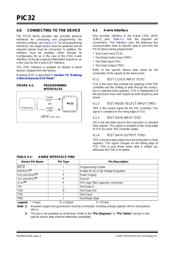
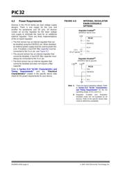
An external tool programming setup consists of an
external programmer tool and a target PIC32 device.
Figure 2-1 illustrates a typical programming setup. The
programmer tool is responsible for executing
necessary programming steps and completing the
programming operation.
FIGURE 2-1: PROGRAMMING SYSTEM
SETUP
2.1 Devices with Dual Flash Panel and
Dual Boot Regions
The PIC32MK and PIC32MZ families of devices
incorporate several features useful for field (self)
programming of the device. These features include
dual Flash panels with dual boot regions, an aliasing
scheme for the boot regions allowing automatic
selection of boot code at start-up and a panel swap
feature for Program Flash. The two Flash panels and
their associated boot regions can be erased and
programmed separately. Refer to Section 48.
“Memory Organization and Permissions”
(DS60001214) of the “PIC32 Family Reference
Manual” for a detailed explanation of these features.
A development tool used for production programming
will not be concerned about most of these features with
the following exceptions:
• Ensuring the SWAP bit (NVMCON<7>) is in the
proper setting. The default setting is ‘0’ for no swap
of panels. The development tool should assume the
default setting when generating source files for the
programming tool.
• Proper handling of the aliasing of the boot memory
in the checksum calculation. The aliased sections
will be duplicates of the fixed sections. See
Section 18.0 “Checksum” for more information on
checksum calculations with aliased regions.
Target PIC32 Device
CPU
On-Chip Memory
External
Programmer
PIC32 Flash Programming Specification
Verzeichnis