

herunterladen
GND
GND
V
IN
V
CC
PP
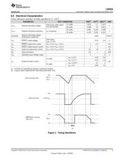
INPUT
RESET
RESET
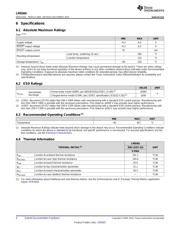
* 470k:
C
D
C
D
* REQUIRED FOR OPEN DRAIN OUTPUT
Product
Folder
Sample &
Buy
Technical
Documents
Tools &
Software
Support &
Community
An IMPORTANT NOTICE at the end of this data sheet addresses availability, warranty, changes, use in safety-critical applications,
intellectual property matters and other important disclaimers. PRODUCTION DATA.
LM8365
SNVS233C –MARCH 2003–REVISED DECEMBER 2015
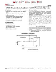
LM8365 Micropower Undervoltage-Sensing Circuit With Programmable Output Delay
1
1 Features
1
• Extremely-Low Quiescent Current: 0.62 μA at V
IN
= 2.6 V
• High Accuracy Threshold Voltage (±2.5%)
• Open-Drain Output
• Programmable Output Delay by External
Capacitor (130 ms Typical With 0.1 μF)
• Input Voltage Range: 1 V to 6 V
• Pin-for-Pin Compatible With MC33465
2 Applications
• Portable Electronics
• Low-Battery Detection
• Microprocessor Reset Controllers
• Power Fail Indicators
• Battery Backup Detection
3 Description
The LM8365 device is a micropower undervoltage
sensing circuit that is ideal for use in battery-powered
microprocessor based systems, where extended
battery life is a key requirement.
Threshold voltages of 2.7 V and 4.5 V are available
with an active-low, open-drain output. These devices
feature a very-low quiescent current of 0.65 µA
typical. The LM8365 features a highly accurate
voltage reference, a comparator with precise
thresholds and built-in hysteresis to prevent erratic
reset operation, a time delayed output which can be
programmed by the system designer, and specified
Reset operation down to 1 V with extremely-low
standby current.
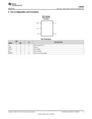
Device Information
(1)
PART NUMBER PACKAGE BODY SIZE (NOM)
LM8365 SOT-23 (5) 2.90 mm × 1.60 mm
(1) For all available packages, see the orderable addendum at
the end of the data sheet.
Microprocessor Reset Circuit
Verzeichnis
- ・ Konfiguration des Pinbelegungsdiagramms on Seite 3
- ・ Abmessungen des Paketumrisses on Seite 17 Seite 19 Seite 20
- ・ Markierungsinformationen on Seite 17
- ・ Blockdiagramm on Seite 9
- ・ Typisches Anwendungsschaltbild on Seite 11
- ・ Technische Daten on Seite 4
- ・ Anwendungsbereich on Seite 1 Seite 22
- ・ Elektrische Spezifikation on Seite 4 Seite 5