
herunterladen
CAT5114
© 2009 SCILLC. All rights reserved. 1 Doc. No. MD-2007 Rev. S
Characteristics subject to change without notice
32-Tap Digitally Programmable Potentiometer (DPP™)
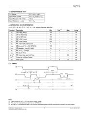
FEATURES
32-position linear taper potentiometer
Non-volatile EEPROM wiper storage
Low standby current
Single supply operation: 2.5 V – 6 V
Increment up/down serial interface
Resistance values: 10 kΩ, 50 kΩ and 100 kΩ
Available in PDIP, SOIC, TSSOP, MSOP and
space saving 2 x 2.5 mm TDFN packages
APPLICATIONS
Automated product calibration
Remote control adjustments
Offset, gain and zero control
Tamper-proof calibrations
Contrast, brightness and volume controls
Motor controls and feedback systems
Programmable analog functions
For Ordering Information details, see page 14.
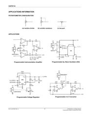
DESCRIPTION
The CAT5114 is a single digitally programmable
potentiometer (DPP™) designed as a electronic
replacement for mechanical potentiometers and trim
pots. Ideal for automated adjustments on high volume
production lines, they are also well suited for
applications where equipment requiring periodic
adjustment is either difficult to access or located in a
hazardous or remote environment.
The CAT5114 contains a 32-tap series resistor array
connected between two terminals R
H
and R
L
. An up/
down counter and decoder that are controlled by three
input pins, determines which tap is connected to the
wiper, R
W
. The wiper setting, stored in nonvolatile
memory, is not lost when the device is powered down
and is automatically reinstated when power is
returned. The wiper can be adjusted to test new
system values without affecting the stored setting.
Wiper-control of the CAT5114 is accomplished with
three input control pins, CS
¯¯
, U/D
¯
, and INC
¯¯¯
. The INC
¯¯¯
input increments the wiper in the direction which is
determined by the logic state of the U/D
¯
input. The CS
¯¯
input is used to select the device and also store the
wiper position prior to power down.
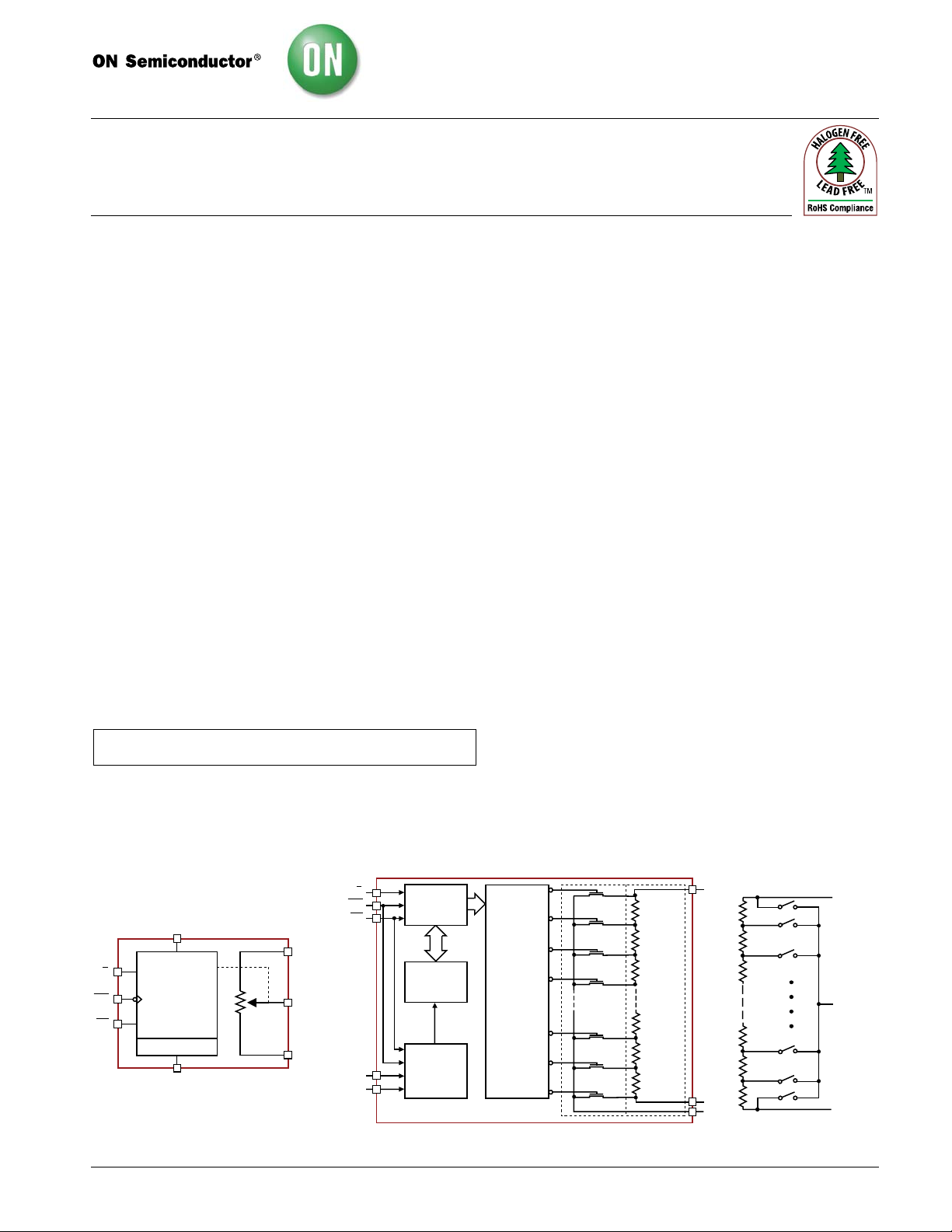
The digitally programmable potentiometer can be
used as a three-terminal resistive divider or as a two-
terminal variable resistor. DPPs bring variability and
programmability to a wide variety of applications
including control, parameter adjustments, and signal
processing.
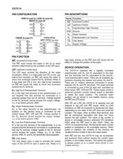
FUNCTIONAL DIAGRAM
R
H
/V
H
R
L
/V
L
Control
and
Memory
Power On Recall
V
CC
GND
U/D
INC
CS
R
H
/V
H
R
L
/V
L
R
W
/V
W
R
W
/V
W
Electronic Potentiometer
Implementation
DetailedGeneral
32-POSITION
DECODER
31
30
29
28
2
1
0
TRANSFER
GATES
RESISTOR
ARRAY
5-BIT
NONVOLATILE
MEMORY
STORE AND
RECALL
CONTROL
CIRCUITRY
5-BIT
UP/DOWN
COUNTER
V
CC
GND
R
H
/V
H
R
W
/V
W
R
L
/V
L
U/D
INC
CS
Verzeichnis
- ・ Konfiguration des Pinbelegungsdiagramms on Seite 2
- ・ Abmessungen des Paketumrisses on Seite 8
- ・ Teilenummerierungssystem on Seite 1 Seite 14
- ・ Typisches Anwendungsschaltbild on Seite 1
- ・ Technische Daten on Seite 3
- ・ Anwendungsbereich on Seite 1 Seite 6
- ・ Elektrische Spezifikation on Seite 3
- ・ Teilenummernliste on Seite 14