
herunterladen

74HC6323A; 74HCT6323A
Programmable ripple counter with oscillator; 3-state
Rev. 4 — 9 July 2018 Product data sheet
1 General description
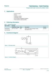
The 74HC6323A; 74HCT6323A is an oscillator designed for quartz crystal combined with
a programmable 3-state counter, a 3-state output buffer and an overriding asynchronous
master reset (MR). With the two select inputs S1 and S2 the counter can be switched
in the divide-by-1, 2, 4 or 8 mode. If left floating the clock is divided by 8. The oscillator
is designed to operate either in the fundamental or third overtone mode depending on
the crystal and external components applied. On-chip capacitors minimize external
component count for third overtone crystal applications. The oscillator may be replaced
by an external clock signal at input X1. In this event the other oscillator pin (X2) must
be floating. The counter advances on the negative-going transition of X1. A LOW level
on MR resets the counter, stops the oscillator and sets the output buffer in the 3-state
condition. MR can be left floating since an internal pull-up resistor will make the MR
inactive.
The X1 input has CMOS input switching levels and may be driven by a TTL output using
a pull-up resistor connected to V
CC
. Inputs include clamp diodes. This enables the use of
current limiting resistors to interface inputs to voltages in excess of V
CC
.
2 Features and benefits
• Programmable 3-stage ripple counter
• Suitable for over-tone crystal application up to 50 MHz (V
CC
= 5 V ± 10%)
• 3-state output buffer
• Two internal capacitors
• Recommended operating range for use with third overtone crystals 3 to 6 V
• Oscillator stop function (MR)
• Input levels:
– For 74HC6323: CMOS level
– For 74HCT6323: TTL level
• ESD protection:
– HBM JESD22-A114-A exceeds 2000 V
– MM JESD22-A115-A exceeds 200 V
• Specified from -40 °C to +85 °C and from -40 °C to +125 °C
Verzeichnis
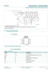
- ・ Konfiguration des Pinbelegungsdiagramms on Seite 3
- ・ Abmessungen des Paketumrisses on Seite 18
- ・ Teilenummerierungssystem on Seite 2
- ・ Typisches Anwendungsschaltbild on Seite 2 Seite 3 Seite 16
- ・ Beschreibung der Funktionen on Seite 1 Seite 4
- ・ Technische Daten on Seite 20
- ・ Anwendungsbereich on Seite 2 Seite 20