
herunterladen

User's Guide
SLVUA72–June 2014
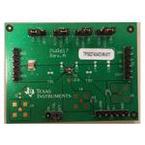
TPS82740xEVM-617
This user’s guide describes the characteristics, operation, and use of the Texas Instruments TPS82740x
evaluation module (EVM). This EVM is designed to help the user easily evaluate and test the operation
and functionality of the TPS82740x. The EVM converts a 2.2-V to 5.5-V input voltage to a regulated output
voltage that is set between 1.8 V and 2.5 V (TPS82740A) or 2.6 V to 3.3 V (TPS82740B) at up to 200 mA.
The TPS82740x also includes a load switch and features an ultra-low quiescent current of 360 nA. This
user’s guide includes setup instructions for the hardware, a printed-circuit board layout for the EVM, a
schematic diagram, and a bill of materials.
Contents
1 Introduction ................................................................................................................... 2
1.1 Features.............................................................................................................. 2
1.2 Applications.......................................................................................................... 2
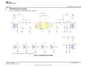
2 TPS82740xEVM-617 Schematic........................................................................................... 3
3 Connector and Test Point Descriptions................................................................................... 4
3.1 J1 Input Connectors................................................................................................ 4
3.2 J2 Output Connector ............................................................................................... 4
3.3 J3 Load Connector ................................................................................................. 4
3.4 Other Connectors................................................................................................... 5
3.5 Jumpers.............................................................................................................. 5
4 TPS82740xEVM Assembly Drawings and Layout....................................................................... 7
5 Bill of Materials............................................................................................................... 9
List of Figures
1 TPS82740xEVM Schematic................................................................................................ 3
2 TPS82740xEVM Component Placement (Top View) ................................................................... 7
3 TPS82740xEVM Top-Side Copper (Top View).......................................................................... 7
4 TPS82740xEVM Inner Layer 1 Copper (Top View)..................................................................... 8
5 TPS82740xEVM Inner Layer 2 Copper (Top View)..................................................................... 8
6 TPS82740xEVM Bottom-Side Copper (Top View) ...................................................................... 8
List of Tables
1 TPS82740xEVM-617 Bill of Materials..................................................................................... 9
1
SLVUA72–June 2014 TPS82740xEVM-617
Submit Documentation Feedback
Copyright © 2014, Texas Instruments Incorporated
Verzeichnis
- ・ Blockdiagramm on Seite 3
- ・ Anwendungsbereich on Seite 2 Seite 10 Seite 13