
herunterladen

User's Guide
SLVU958–August 2013
4.5-V to 18-V Input, 6-A and 3.5-A Dual Synchronous
Step-Down Converter Evaluation Module
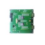
This document is provided with the TPS65276 PMIC evaluation module (EVM) as a supplement to the
TPS65276 data sheet. This user's guide includes the schematic, hardware setup, software installation and
bill of materials (BOM).
Contents
1 Introduction .................................................................................................................. 2
2 Background .................................................................................................................. 2
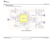
3 TPS65276 Schematic ...................................................................................................... 3
4 Board Layout ................................................................................................................ 4
5 Bench Test Setup Conditions ............................................................................................. 7
5.1 Header Description and Jumper Placement .................................................................... 7
6 Power-Up Procedure ....................................................................................................... 8
7 EVM Bill of Materials ....................................................................................................... 9
List of Figures
1 TPS65276 Schematic ...................................................................................................... 3
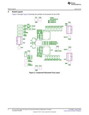
2 Component Placement (Top Layer) ...................................................................................... 4
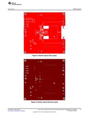
3 Board Layout (Top Layer).................................................................................................. 5
4 Board Layout (Second Layer)............................................................................................. 5
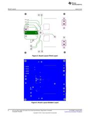
5 Board Layout (Third Layer)................................................................................................ 6
6 Board Layout (Bottom Layer).............................................................................................. 6
7 Header Description and Jumper Placement............................................................................. 7
List of Tables
1 Summary of Performance.................................................................................................. 2
2 Input/Output Connection ................................................................................................... 7
3 Jumpers and Switches ..................................................................................................... 8
4 EVM Bill of Materials ....................................................................................................... 9
1
SLVU958–August 2013 4.5-V to 18-V Input, 6-A and 3.5-A Dual Synchronous Step-Down Converter
Evaluation Module
Submit Documentation Feedback
Copyright © 2013, Texas Instruments Incorporated
Verzeichnis