
herunterladen

User's Guide
SLVU332–October 2009
TPS61086EVM-526
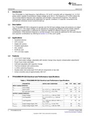
This user's guide describes the characteristics, operation, and use of the TPS61086 evaluation module
(EVM). This EVM contains the Texas Instruments 1.2-MHz, 18.5-V, step-up DC-DC converter TPS61086
with a switch current of 2 A, minimum. The user's guide includes EVM specifications, recommended test
setup, the schematic diagram, bill of materials, and the board layout.
Contents
1 Introduction .................................................................................................................. 2
1.1 Description .......................................................................................................... 2
1.2 Applications ......................................................................................................... 2
1.3 Features ............................................................................................................. 2
2 TPS61086EVM-526 Electrical and Performance Specifications ...................................................... 2
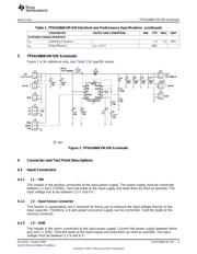
3 TPS61086EVM-526 Schematic ........................................................................................... 3
4 Connector and Test Point Descriptions .................................................................................. 3
4.1 Input Connectors ................................................................................................... 3
4.2 Output Connectors ................................................................................................. 4
4.3 Jumpers ............................................................................................................. 4
5 Test Setup ................................................................................................................... 4
5.1 EVM Operation ..................................................................................................... 4
5.2 Compensation – COMP ........................................................................................... 4
6 TPS61086EVM-526 Assembly Drawings and Layout .................................................................. 5
7 List of Materials ............................................................................................................. 7
List of Figures
1 TPS61086EVM-526 Schematic ........................................................................................... 3
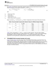
2 TPS61086EVM-526 Component Placement; Viewed From Top ..................................................... 6
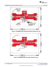
3 TPS61086EVM-526 Top Copper; Viewed From Top .................................................................. 7
4 TPS61086EVM-526 Bottom Copper; Viewed From Bottom........................................................... 7
List of Tables
1 TPS61086EVM-526 Electrical and Performance Specifications...................................................... 2
2 Recommended Compensation Network Values for Different Output Voltages..................................... 5
3 TPS61086EVM-526 Bill of Materials ..................................................................................... 7
1
SLVU332–October 2009 TPS61086EVM-526
Submit Documentation Feedback
Copyright © 2009, Texas Instruments Incorporated
Verzeichnis
- ・ Blockdiagramm on Seite 3
- ・ Technische Daten on Seite 2 Seite 3
- ・ Anwendungsbereich on Seite 2 Seite 9