
herunterladen
User's Guide
SLVU962–November 2013
TPS54388EVM User's Guide
The TPS54388-Q1 DC-DC converter is designed to provide up to a 3-A output from an input voltage
source of 2.95 V to 6 V. Table 1 lists the ratings for the input-voltage and output-current range of the
evaluation module (EVM). This evaluation module is designed to demonstrate the small printed-circuit-
board (PCB) areas that can be achieved when designing with the TPS54388-Q1 regulator. The switching
frequency is externally set at a nominal 2000 kHz. The high-side and low-side MOSFETs are incorporated
inside the TPS54388-Q1 device to achieve high efficiencies and to maintain a low junction temperature at
high output currents. The compensation components are external to the integrated circuit (IC) and have
been selected to optimize the transient performance of the device. An external divider allows for an
adjustable output voltage. Additionally, the TPS54388-Q1 device provides adjustable slow-start and
undervoltage lockout inputs. The absolute-maximum input voltage is 7 V for the TPS54388EVM.
Table 1. Input Voltage and Output Current Summary
EVM Input Voltage Range Output current Range
TPS54388EVM V
IN
= 3 V to 6 V 0 A to 3 A
Contents
1 Performance-Specification Summary .................................................................................... 2
2 Test Setup and Results .................................................................................................... 3
3 Board Layout ................................................................................................................ 8
4 Schematic and Bill of Materials .......................................................................................... 11
List of Figures
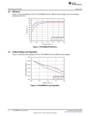
1 TPS54388EVM Efficiency.................................................................................................. 4
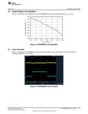
2 TPS54388EVM Load Regulation ......................................................................................... 4
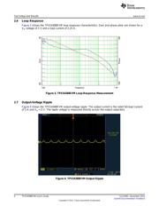
3 TPS54388EVM Line Regulation .......................................................................................... 5
4 TPS54388EVM Load Transient........................................................................................... 5
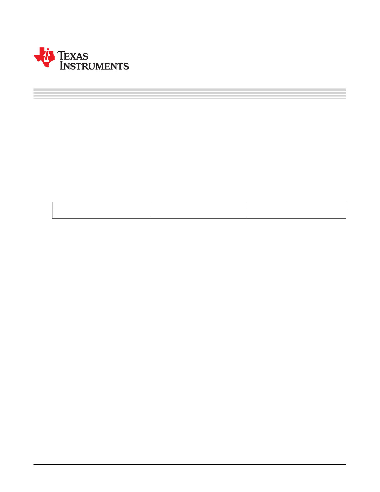
5 TPS54388EVM Loop-Response Measurement......................................................................... 6
6 TPS54388EVM Output Ripple ............................................................................................ 6
7 TPS54388EVM Startup Relative to V
IN
.................................................................................. 7
8 TPS54388EVM Startup Relative to Enable.............................................................................. 7
9 TPS54388EVM Top-Side Layout ......................................................................................... 8
10 TPS54388EVM Bottom-Side Layout ..................................................................................... 9
11 TPS54388EVM Top-Side Assembly...................................................................................... 9
12 TPS54388EVM Bottom-Side Assembly ................................................................................ 10
13 TPS54388EVM Schematic............................................................................................... 11
List of Tables
1 Input Voltage and Output Current Summary ............................................................................ 1
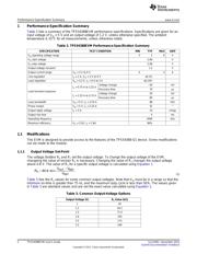
2 TPS54388EVM Performance-Specification Summary................................................................. 2
3 Common Output-Voltage Options ........................................................................................ 2
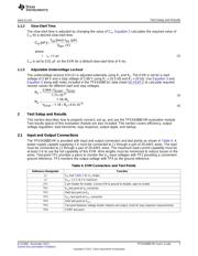
4 EVM Connectors and Test Points ........................................................................................ 3
5 TPS54388EVM Bill of Materials ......................................................................................... 12
1
SLVU962–November 2013 TPS54388EVM User's Guide
Submit Documentation Feedback
Copyright © 2013, Texas Instruments Incorporated
Verzeichnis
- ・ Blockdiagramm on Seite 11 Seite 12
- ・ Technische Daten on Seite 2
- ・ Anwendungsbereich on Seite 13