
herunterladen

User's Guide
SLVU147A – February 2006 – Revised March 2006
Using the TPS40200
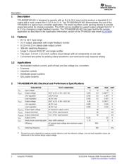
The TPS40200EVM-001 evaluation module (EVM) uses the TPS40200
nonsynchronous buck converter to provide a resistor-selected 3.3-V output voltage that
delivers up to 2.5 A from a 12-V input bus. The EVM operates from a single supply and
uses a single P-channel power FET and Schottky diode to produce a low-cost buck
converter. The part operates at a 300-kHz clock frequency with provision for external
frequency synchronization.
Contents
1 Description ........................................................................................... 2
2 TPS40200EVM-001 Electrical and Performance Specifications ............................. 2
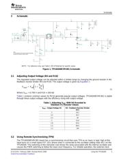
3 Schematic ........................................................................................... 3
4 Test Setup ........................................................................................... 4
5 TPS40200EVM Typical Performance Data and Characteristic Curves ..................... 7
6 EVM Assembly Drawings and Layout ........................................................... 9
7 List of Materials .................................................................................... 14
List of Figures
1 TPS40200EVM-001 Schematic ................................................................... 3
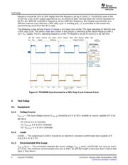
2 TPS40200 Synchronized to a 50% Duty Cycle External Clock .............................. 4
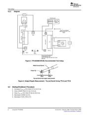
3 TPS40200EVM-001 Recommended Test Setup ............................................... 6
4 Output Ripple Measurement - Tip and Barrel Using TP14 and TP15 ....................... 6
5 TPS40200EVM-001 Efficiency .................................................................... 7
6 TPS40200EVM-001 Efficiency .................................................................... 8
7 TPS40200EVM-001 Line and Load Regulation – Vout = 3.3255 V .......................... 8
8 TPS40200EVM-001 Line and Load Regulation – Vout = 5.0665 V ......................... 9
9 TPS40200EVM-001 Component Placement (Viewed from Top) ........................... 10
10 TPS40200EVM-001 Silkscreen (Viewed from Top) .......................................... 11
11 TPS40200EVM-001 Top View .................................................................. 12
12 TPS40200EVM-001 Bottom View ............................................................... 13
List of Tables
1 Adjusting V
OUT
With R6 Rounded to Standard 1% Resistor Values ......................... 3
2 TPS40200EVM-001 Bill of Materials ........................................................... 14
SLVU147A – February 2006 – Revised March 2006 Using the TPS40200 1
Submit Documentation Feedback
Verzeichnis
- ・ Blockdiagramm on Seite 3
- ・ Technische Daten on Seite 2
- ・ Anwendungsbereich on Seite 2 Seite 16
- ・ Elektrische Spezifikation on Seite 7 Seite 8