
herunterladen

TMS320DM642
www.ti.com
SPRS200N–JULY 2002–REVISED OCTOBER 2010
TMS320DM642
Video/Imaging Fixed-Point Digital Signal Processor
Check for Samples: TMS320DM642
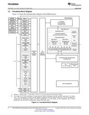
1 TMS320DM642 Video/Imaging Fixed-Point Digital Signal Processor
123
– 1024M-Byte Total Addressable External
• High-Performance Digital Media Processor
Memory Space
– 2-, 1.67-, 1.39-ns Instruction Cycle Time
• Enhanced Direct-Memory-Access (EDMA)
– 500-, 600-, 720-MHz Clock Rate
Controller (64 Independent Channels)
– Eight 32-Bit Instructions/Cycle
• 10/100 Mb/s Ethernet MAC (EMAC)
– 4000, 4800, 5760 MIPS
– IEEE 802.3 Compliant
– Fully Software-Compatible With C64x™
– Media Independent Interface (MII)
• VelociTI.2™ Extensions to VelociTI™
– 8 Independent Transmit (TX) Channels and 1
Advanced Very-Long-Instruction-Word (VLIW)
Receive (RX) Channel
TMS320C64x™ DSP Core
• Management Data Input/Output (MDIO)
– Eight Highly Independent Functional Units
• Three Configurable Video Ports
With VelociTI.2™ Extensions:
– Providing a Glueless I/F to Common Video
• Six ALUs (32-/40-Bit), Each Supports
Decoder and Encoder Devices
Single 32-Bit, Dual 16-Bit, or Quad 8-Bit
Arithmetic per Clock Cycle – Supports Multiple Resolutions/Video Stds
• Two Multipliers Support Four 16 x 16-Bit • VCXO Interpolated Control Port (VIC)
Multiplies (32-Bit Results) per Clock
– Supports Audio/Video Synchronization
Cycle or Eight 8 x 8-Bit Multiplies (16-Bit
• Host-Port Interface (HPI) [32-/16-Bit]
Results) per Clock Cycle
• 32-Bit/66-MHz, 3.3-V Peripheral Component
– Load-Store Architecture With Non-Aligned
Interconnect (PCI) Master/Slave Interface
Support
Conforms to PCI Specification 2.2
– 64 32-Bit General-Purpose Registers
• Multichannel Audio Serial Port (McASP)
– Instruction Packing Reduces Code Size
– Eight Serial Data Pins
– All Instructions Conditional
– Wide Variety of I
2
S and Similar Bit Stream
• Instruction Set Features
Formats
– Byte-Addressable (8-/16-/32-/64-Bit Data)
– Integrated Digital Audio I/F Transmitter
– 8-Bit Overflow Protection Supports S/PDIF, IEC60958-1, AES-3, CP-430
Formats
– Bit-Field Extract, Set, Clear
• Inter-Integrated Circuit ( I
2
C Bus™)
– Normalization, Saturation, Bit-Counting
• Two Multichannel Buffered Serial Ports
– VelociTI.2™ Increased Orthogonality
• Three 32-Bit General-Purpose Timers
• L1/L2 Memory Architecture
• Sixteen General-Purpose I/O (GPIO) Pins
– 128K-Bit (16K-Byte) L1P Program Cache
(Direct Mapped) • Flexible PLL Clock Generator
– 128K-Bit (16K-Byte) L1D Data Cache (2-Way • IEEE-1149.1 (JTAG) Boundary-Scan-Compatible
Set-Associative)
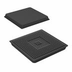
• 548-Pin Ball Grid Array (BGA) Package
– 2M-Bit (256K-Byte) L2 Unified Mapped (GDK and ZDK Suffixes), 0.8-mm Ball Pitch
RAM/Cache (Flexible RAM/Cache Allocation)
• 548-Pin Ball Grid Array (BGA) Package
• Endianess: Little Endian, Big Endian (GNZ and ZNZ Suffixes), 1.0-mm Ball Pitch
• 64-Bit External Memory Interface (EMIF) • 0.13-µm/6-Level Cu Metal Process (CMOS)
– Glueless Interface to Asynchronous • 3.3-V I/O, 1.2-V Internal (-500)
Memories (SRAM and EPROM) and
• 3.3-V I/O, 1.4-V Internal (A-500, A-600, -600,
Synchronous Memories (SDRAM, SBSRAM,
-720)
ZBT SRAM, and FIFO)
1
Please be aware that an important notice concerning availability, standard warranty, and use in critical applications of Texas
Instruments semiconductor products and disclaimers thereto appears at the end of this data sheet.
2Windows is a registered trademark of Microsoft Corporation.
3I
2
C Bus is a trademark of Philips Electronics N.V..
PRODUCTION DATA information is current as of publication date.
Copyright © 2002–2010, Texas Instruments Incorporated
Products conform to specifications per the terms of the Texas
Instruments standard warranty. Production processing does not
necessarily include testing of all parameters.
Verzeichnis
- ・ Konfiguration des Pinbelegungsdiagramms on Seite 16 Seite 63 Seite 64 Seite 65
- ・ Abmessungen des Paketumrisses on Seite 170 Seite 171 Seite 172
- ・ Markierungsinformationen on Seite 170 Seite 171 Seite 172
- ・ Blockdiagramm on Seite 4 Seite 108 Seite 117
- ・ Beschreibung der Funktionen on Seite 55 Seite 56
- ・ Technische Daten on Seite 69 Seite 70 Seite 71 Seite 72 Seite 73
- ・ Anwendungsbereich on Seite 178
- ・ Elektrische Spezifikation on Seite 70 Seite 71 Seite 72 Seite 73 Seite 74