
herunterladen
www.DeltaPSU.com
REV.04
Instruction Manual
1. Safety Instructions
• To ensure sufficient convection cooling, always maintain a safety distance of ≥ 20mm from all
ventilated surfaces while the device is in operation.
• The device is not recommended to be placed on low thermal conductive surface, for example,
plastics.
• Note that the enclosure of the device can become very hot depending on the ambient temperature
and load of the power supply. Do not touch the device while it is in operation or immediately after
power is turned OFF. Risk of burning!
• Do not touch the terminals while power is being supplied. Risk of electric shock.
• Prevent any foreign metal, particles or conductors to enter the device through the openings during
installation. It can cause: - Electric shock; Safety Hazard; Fire; Product failure.
• The power supply must be mounted by metal screws onto a grounded metal surface. It is also
highly recommended that the Earth terminal on the connector be connected to the grounded metal
surface.
• Warning (For Standard Terminal Block and Front Face Terminal Block products): When connecting
the device, secure Earth connection before connecting L and N. When disconnecting the device,
remove L and N connections before removing the Earth connection.
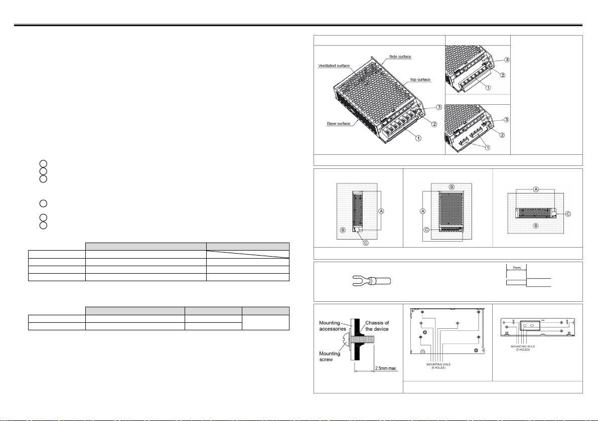
2. Device Descriptions
Refer to Fig. 1.:
1 Input & Output terminal block connector
2 DC voltage adjustment potentiometer
3 DC OK control LED (Green)
3. Installation of the Device
Refer to Fig. 2.:
A Mounting holes for the power supply (device). The device shall be mounted on minimum of 2
mounting holes using M3 screw of minimum 5mm length.
B This surface belongs to customer’s end system or panel where the device is mounted.
C Connector
• Use flexible cable (stranded or solid) with the following sizes:
Table 1:
PM☐-☐V100W1AA / PM☐-☐V100W1AG
PM☐-☐V100W1AH
5V
AWG 14-12
7.5-9V
AWG 18-12
AWG 18
12V
AWG 20-12
AWG 20-18
15-48V
AWG 22-12
AWG 22-18
• PM☐-☐V100W1AA / PM☐-☐V100W1AG: The torque at the Connector shall not exceed 13Kgf.cm.
The insulation stripping length should not exceed 0.275” or 7mm (Refer to Fig. 3).
• PM☐-☐V100W1AH: Please refer to Table 2 for the recommended Housing and Terminal.
Table 2:
Connector (Board Mounting)
Housing
Terminal
Input (JWT)
A3963WV2-5P-A
A3963H02-5P
A3963T0P-2
Output (JWT)
A3963WV2-7P-U
A3963H02-7P
4. Installation of Mounting Accessories
• With reference to Fig. 4, only use M3 screw ≤ 2.5mm through the base or side mounting holes.
This is to keep a safe distance between the screw and internal components.
• With reference to Fig. 5, the device should be mounted on a sturdy heat conducting surface with
minimum of 4 mounting holes using M3 screw through the base or side mounting holes.
• Recommended mounting tightening torque: 4~7Kgf.cm.
PM☐-☐V100W1A☐*
Side Mounting (Horizontal)
Base Mounting (Vertical)
Fig. 2. Mounting Orientation
Side Mounting (Vertical)
(PM
☐
-
☐
V100W1AA / PM
☐
-
☐
V100W1AG)
Fig. 3. Wire Type
Stripped wire
Lug
Fig. 1. Device Descriptions
PMT-☐V100W1AA
PMT-☐V100W1AG
PMT-☐V100W1AH
• PMT-☐V100W1AA:
Standard Terminal Block
• PMT-
☐
V100W1AG:
Front Face Terminal Block
• PMT-
☐
V100W1AH:
Harness Connector
• PML-
☐
V100W1AA/AG/AH:
L Frame (without cover)
Base Mounting
Side Mounting
Fig. 4. Mounting Screw
Fig. 5. Mounting Hole Locations
*Not applicable for PMC series