
herunterladen
© Semiconductor Components Industries, LLC, 2013
August, 2013 − Rev. 1
1 Publication Order Number:
EVBUM2198/D
NCV7430GEVB
NCV7430 LIN RGB Driver
Using Auto‐addressing and
High Current Evaluation
Board User's Manual
Description
Recent customer requests have shown there is a need for an RGB
lighting driver device to operate in a fashion to allow the system to
assign an address after power-up to allow component changes after the
initial system assembly as an option to pre-programming prior to
assembly at the automotive manufacturer.
The NCV7430 auto-addressing evaluation board uses an approach
where the LIN communication bus is consecutively switched between
modules after an address has been assigned.
The target application for the NCV7430 LIN RGB BIAS pin is
defined for use as a thermal distribution device, but can find a use here
in providing the customer with a solution for auto-addressing of the
system board attached on LIN bus.
Additionally features to the board developed here allows for the
demonstration of external drivers for higher current LEDs and testing
of thermal compensation components as described in the NCV7430/D
data sheet.
Features
In addition to the NCV7430 part features, this evaluation board
highlights the following:
• Auto-addressing
• Increased Output Current
• Temperature Compensation
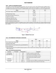
The board shown in Figure 2 has the on-board LED on the bottom
side of the board (U2). The external high current drivers (Q1, Q2, Q3)
for external LED control are not populated.
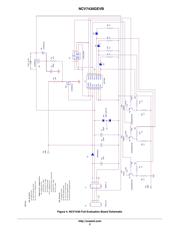
Details of schematic contents can be found in the upper-left portion
of the schematic (see Figure 4).
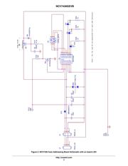
All boards are shipped with zero ohm resistors for D3, D4, and D5.
These can be replaced by customer specific schottky diodes for
thermal compensation.
WARNING: This board should only be used for driving EITHER an external
LED with the NJVMJD253T4G drivers or the on-board
LRTB_G6TG LED.
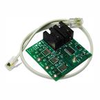
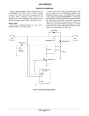
Figure 3. Evaluation Board
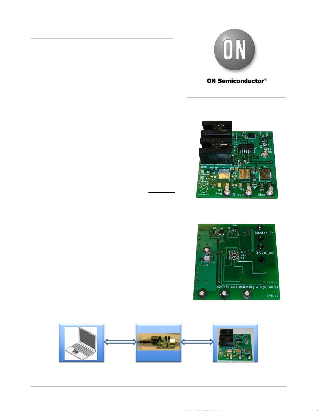
PC
USB Interface
Connector
Target BoardUSB2SPI Adapter
http://onsemi.com
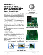
EVAL BOARD USER’S MANUAL
Figure 1. Evaluation Board − Top View
Figure 2. Evaluation Board − Bottom View
Verzeichnis