

Semiconductor Components Industries, LLC, 2012
September, 2012 − Rev. 3
1 Publication Order Number:
EVBUM2099/D
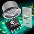
NCL30000LED1GEVB
90-135 Vac up to 15 Watt
Dimmable LED Driver
Evaluation Board
User's Manual
Introduction
The NCL30000 is a power factor corrected LED driver
controller. This evaluation board manual describes the setup
and operation of the NCL30000LED1GEVB LED driver for
115 V input. The evaluation board implements an isolated
single stage Critical conduction Mode (CrM) flyback
converter providing a regulated constant current to an LED
load. This board has been specifically configured to support
leading and trailing edge line dimming and has been
characterized across a range of commercially available
dimmers. The output voltage range is suitable for nominal
4 to 15 high brightness power LEDs. Protection features
include open load protection, over temperature protection,
and overload limiting. As shipped, the evaluation board is
set up for the following parameters:
Evaluation Board Specifications
Input Voltage Range: 90−135 Vac
Output Current: 350 mA 5%
Output Voltage Range: 12−50 Vdc
Output Power: up to 17.5 W
Full Load Efficiency: >83%
Power Factor: >0.95 Typical
50C Ambient Operation
Class B Conducted Emissions
Compatible with Triac and Electronic Dimmers
This manual also focuses on how the board can be
modified to support alternate output currents and power
levels. The NCL30000 datasheet contains additional
information on operation of the controller and LED driver
application. Application Note AND8451 details power
stage design details and AND8448 provides specific
information for dimming applications. Design calculations
are covered in greater detail in these documents.
The compact evaluation board is constructed with
through-hole components on the top and surface mount
components on the bottom side. This board was designed to
meet safety agency requirements but has not been evaluated
for compliance. When operating this board, observe
standard safe working practices. High voltages are present
on the board and caution should be exercised when handling
or probing various points to avoid personal injury or damage
to the unit.
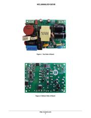
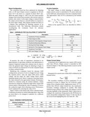
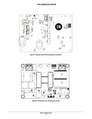
Figures 1 and 2 show the top and bottom sides of this
evaluation board. AC input connects to the terminal block in
the upper left corner. Terminals are marked “L” and “N” for
Line and Neutral. The LED load connects to the terminal
block in the upper right corner. Note the board is labeled
“LED+” and “LED−“. Observe polarity when connecting
LED loads. Never connect LEDs to the driver while it is
running or before the output capacitors discharge after
removing input power. In open load conditions the output
capacitors charge to >56 V. Energy stored in the output
capacitance can damage or shorten the effective life of the
LEDs if improperly discharged into the LEDs.
http://onsemi.com
EVAL BOARD USER’S MANUAL
Verzeichnis
- ・ Teilenummerierungssystem on Seite 10
- ・ Markierungsinformationen on Seite 10
- ・ Blockdiagramm on Seite 3
- ・ Technische Daten on Seite 1
- ・ Anwendungsbereich on Seite 4 Seite 6