
herunterladen

Product
Folder
Sample &
Buy
Technical
Documents
Tools &
Software
Support &
Community
Reference
Design
An IMPORTANT NOTICE at the end of this data sheet addresses availability, warranty, changes, use in safety-critical applications,
intellectual property matters and other important disclaimers. PRODUCTION DATA.
MSP430G2533
,
MSP430G2433
,
MSP430G2333
,
MSP430G2233
MSP430G2403, MSP430G2303, MSP430G2203
SLAS734G –APRIL 2011–REVISED APRIL 2016
MSP430G2x33, MSP430G2x03 Mixed-Signal Microcontrollers
1 Device Overview
1
1.1 Features
1
• Low Supply-Voltage Range: 1.8 V to 3.6 V
• Ultra-Low Power Consumption
– Active Mode: 230 µA at 1 MHz, 2.2 V
– Standby Mode: 0.5 µA
– Off Mode (RAM Retention): 0.1 µA
• Five Power-Saving Modes
• Ultra-Fast Wake up From Standby Mode in Less
Than 1 µs
• 16-Bit RISC Architecture, 62.5-ns Instruction Cycle
Time
• Basic Clock Module Configurations
– Internal Frequencies up to 16 MHz With Four
Calibrated Frequencies
– Internal Very-Low-Power Low-Frequency (LF)
Oscillator
– 32-kHz Crystal
– External Digital Clock Source
• Two 16-Bit Timer_A With Three Capture/Compare
Registers
• Up to 24 Capacitive-Touch Enabled I/O Pins
• Universal Serial Communication Interface (USCI)
– Enhanced UART Supports Automatic Baud-
Rate Detection (LIN)
– IrDA Encoder and Decoder
– Synchronous SPI
– I
2
C
• 10-Bit 200-ksps Analog-to-Digital Converter (ADC)
With Internal Reference, Sample-and-Hold, and
Autoscan (See Table 3-1)
• Brownout Detector
• Serial Onboard Programming,
No External Programming Voltage Needed,
Programmable Code Protection by Security Fuse
• On-Chip Emulation Logic With Spy-Bi-Wire
Interface
• Section 3 Summarizes Available Family Members
• Package Options
– TSSOP: 20 Pin, 28 Pin
– PDIP: 20 Pin
– QFN: 32 Pin
• For Complete Module Descriptions, See the
MSP430x2xx Family User’s Guide (SLAU144)
1.2 Applications
• Power Management
• Sensor Interface
• Capacitive Touch
1.3 Description
The TI MSP family of ultra-low-power microcontrollers consists of several devices that feature different
sets of peripherals targeted for various applications. The architecture, combined with five low-power
modes, is optimized to achieve extended battery life in portable measurement applications. The device
features a powerful 16-bit RISC CPU, 16-bit registers, and constant generators that contribute to
maximum code efficiency. The digitally controlled oscillator (DCO) allows the device to wake up from low-
power modes to active mode in less than 1 µs.
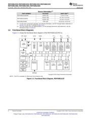
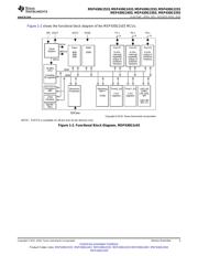
The MSP430G2x03 and MSP430G2x33 devices are ultra-low-power mixed-signal microcontrollers with
built-in 16-bit timers, up to 24 I/O capacitive-touch enabled pins, and built-in communication capability
using the USCI. In addition, the MSP430G2x33 family members have a 10-bit ADC. See Section 3 for
configuration details.
Typical applications include low-cost sensor systems that capture analog signals, convert them to digital
values, and then process the data for display or for transmission to a host system.
Verzeichnis
- ・ Konfiguration des Pinbelegungsdiagramms on Seite 8 Seite 49 Seite 51 Seite 53 Seite 55
- ・ Abmessungen des Paketumrisses on Seite 6 Seite 73 Seite 74 Seite 75 Seite 77
- ・ Markierungsinformationen on Seite 65 Seite 73 Seite 74 Seite 75 Seite 76
- ・ Blockdiagramm on Seite 2 Seite 3
- ・ Typisches Anwendungsschaltbild on Seite 1
- ・ Technische Daten on Seite 13 Seite 14 Seite 15 Seite 16 Seite 17
- ・ Anwendungsbereich on Seite 1 Seite 88