


herunterladen
EVAL-ADG5412BFEBZ User Guide
UG-732
One Technology Way • P. O. Box 9106 • Norwood, MA 02062-9106, U.S.A. • Te l: 781.329.4700 • Fax: 781.461.3113 • www.analog.com
Evaluation Board for the ADG5412BF, Bidirectional Overvoltage Protected Quad SPST
PLEASE SEE THE LAST PAGE FOR AN IMPORTANT
WARNING AND LEGAL TERMS AND CONDITIONS.
Rev. A | Page 1 of 8
FEATURES
Supply voltages
Dual supply: ±5 V to ±22 V
Single supply: 8 V to 44 V
Protected against overvoltage on switch pins
Signal voltages up to −55 V and +55 V
LED for visual overvoltage indication
Parallel interface compatible with 3 V logic
On-board LDO regulator for digital supply and control,
if required
EVALUATION KIT CONTENTS
EVAL-ADG5412BFEBZ evaluation board
DOCUMENTS NEEDED
ADG5412BF data sheet
EVAL-ADG5412BFEBZ user guide
EQUIPMENT NEEDED
DC voltage source
±22 V for dual supply
44 V for single supply
Optional digital voltage source: 3 V to 5 V
Analog signal source
Method to measure voltage, such as a DMM
GENERAL DESCRIPTION
The EVAL-ADG5412BFEBZ is the evaluation board for the
ADG5412BF, which features four independently controlled
single-pole/single-throw (SPST) switches. The ADG5412BF has
overvoltage detection and protection circuitry on the switch
pins and is protected against signals up to −55 V and +55 V in
both the powered and unpowered states.
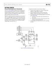
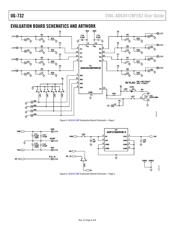
Figure 1 shows the EVAL-ADG5412BFEBZ in a typical evaluation
setup. The ADG5412BF is soldered to the center of the evaluation
board, and four wire screw terminals are provided to connect to
each of the source and drain pins. Three screw terminals are used
to power the device, with a fourth terminal used to provide a user
defined digital voltage, if required. Alternatively, a low dropout
(LDO) regulator is provided for 5 V digital voltage control and
to supply the LED, which is mounted to provide visual indication
of the fault status of the switch.
Full specifications on the ADG5412BF are available in the product
data sheet, which should be consulted in conjunction with this
user guide when using the evaluation board.
TYPICAL EVALUATION SETUP
12483-001
Figure 1. EVAL-ADG5412BFEBZ (on Right), Power Supply, and Signal Generator
Verzeichnis