
herunterladen

Maxim > Design Support > Technical Documents > Reference Designs > Filter Circuits (Analog) > APP 2383
Maxim > Design Support > Technical Documents > Reference Designs > Video Circuits > APP 2383
Keywords: HDTV, reconstruction, video filter, DVD video, high definition, reconstruction, anitaliasing,
ypbpr, TV, display, filters, EIA770-3, SMPTE, output, active, op amp, progressive scan, dvd
REFERENCE DESIGN 2383 INCLUDES: Tested Circuit Schematic BOM Description
Active HDTV Reconstruction Filter Lowers Cost
and Improves Performance
Sep 26, 2003
Abstract: In order to preserve the quality of HDTV and progressive DVD video, a bank of three
(RGB/YPbPr), 5-pole reconstruction filters are used to set the 30MHz bandwidth and to provide the
>40dB selectivity required by EIA770-3.
In order to preserve the quality of HDTV and progressive DVD video, a bank of three (RGB/YPbPr), 5-
pole reconstruction filters are used to set the 30MHz bandwidth and to provide the >40dB selectivity
required by EIA770-3.
Historically these filters have been passive L-C types. Because of the steep selectivity of the filter, they
require group-delay compensation. They also require gain to drive the back-terminated output and
isolate the filter and DAC from the load. Because of the difficulty, custom parts, and tuning required, L-C
filters used for these applications are usually purchased at significant cost, which is further burdened by
the cost of buffering.
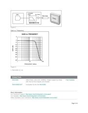
The active-reconstruction filter shown is a lower cost alternative. It uses R-C components, and provides
a 30MHz bandwidth with >40dB rejection at 74.25MHz, as well as group-delay compensation and
buffering using a single MAX4383 quad op amp. The improved tolerance of capacitors (1% to 2%) vs.
inductors (5% to 10%) removes the need for production tuning, although initial component selection is
required to account for the parasitic components of the PCB. The circuit shown uses dual supplies, but
the MAX4383 can use a single supply with appropriate biasing.
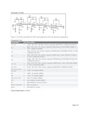
The filter itself is a Rauch, or multiple-feedback realization of a 5-pole, modified Butterworth
characteristic using one first-order +6dB gain stage and two 2nd-order unity-gain stages. The final stage
is a first -order group-delay compensator, which drives the back-terminated 75Ω load to an overall unity
gain. There are three sensitive points in the circuit: R14, which controls the real pole, C1 and C4, which
control the high-frequency poles, and C5, which sets the GD compensation.
R16 and a connector are provided at the input, in place of the DAC load, for measurement purposes.
The DAC load resistance is typically 35Ω to 40Ω, on which the values of R14 and R16 are based. In
some MPEG decoders, this may be as high as 150Ω to 160Ω. To accommodate different DAC load
resistors, adjust the value of the R14, C6 product accordingly. The values of C1 and C4 are small with
respect to the PCBfs parasitic capacity, and reflect a two-sided PCB on FR-4 with 1/2oz, 3/16in-thick
copper with a ground plane around the op-amp pins. C5 adjusts the GD compensation. In laying out this
circuit, it is best to adjust the values of C1 and C4 for bandwidth before adjusting C5 for GD-variation
compensation. A fully configured PCB is available.
Page 1 of 4
Verzeichnis