
herunterladen

Maxim > Design Support > Technical Documents > Application Notes > Battery Management > APP 4721
Keywords: AN4322, Li+ battery simulator, MAX8515, MAX4163
APPLICATION NOTE 4721
The Quick Guide to Layout Considerations for the
Lithium-Ion (Li+) Battery Simulator
By: Shasta Thomas, Applications Engineer
Aug 31, 2010
Abstract:
This application
note describes basic layout guidelines for a Li+ battery charger simulator.
Introduction
Maxim describes a lithium-ion (Li+) battery simulator circuit in application note 4322, "Simplified lithium-ion (Li+)
battery-charger testing." While Maxim does not sell evaluation (EV) boards for this circuit, the Company has
received multiple requests for one. Responding to customer interest, this application note provides some basic
layout guidelines and considerations for designing your own board.
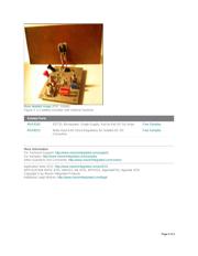
Test Board for the Battery Simulator
Making a board for the Li+ battery simulator does not need to be complicated or expensive. Most of the layout
can be done with a simple two-layer breakout board, however, some consideration does need to be paid to
power connections and heatsinking requirements.
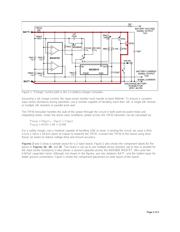
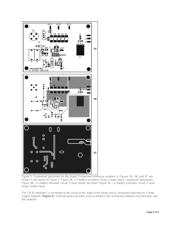
As seen in Figure 1, the major power path of the simulator circuit begins at the BATT+ node, flows through the
100mΩ series input resistance and the TIP35 transistor, and returns at the BATT- node.
Page 1 of 5