
herunterladen
More Information
- Wireless Home
- Application
Notes and Tutorials
- EV Kit Software
- Technical Support
Click here for an overview of the wireless
components used in a typical radio
transceiver.
Maxim > Design Support > Technical Documents > Reference Designs > Microcontrollers > APP 5366
Maxim > Design Support > Technical Documents > Reference Designs > Wireless and RF > APP 5366
Keywords: remote keyless entry, RKE, transmitter, receiver, ISM, RF, radio, PCB, firmware, microcontroller, MCU, battery life, data rate,
automotive, key fob, ASK, modulation, antenna, impedance, C code
REFERENCE DESIGN 5366 INCLUDES: Tested Circuit Schematic BOM Board Available Description Test Data Software Layout
LFRD001: MAX1472/MAX1473/MAXQ610 Remote Keyless Entry
Reference Design
By: Martin Stoehr, Principal Member of the Technical Staff, Applications
Oct 02, 2012
Abstract:
This reference
design provides a complete demonstration platform for using industrial/scientific/medical
(ISM) radio frequency (RF) products in a remote keyless entry (RKE) application. It discusses package size, data
rate, transmit and receive frequency, component value calculation and selection, layout considerations, and
firmware operation. Development steps, system structure, example code, and test results are also provided.
General Description
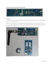
The MAX1472 transmitter and MAX1473 receiver reference design (RD) is a self-contained evaluation
platform for exercising both products as a remote keyless entry (RKE) demonstrator system. With the use of
the MAXQ® USB-to-JTAG board (MAXQJTAG-USB), the MAXQ610 microcontroller on both the transmitter
key fob board and the receiver board can be programmed by the end user.
A simple interface is provided on the transmitter (Tx) board, including four independent momentary switches
and a user feedback LED. The Tx board includes a built-in printed-circuit board (PCB) antenna and operates
off of a single CR2032 coin cell battery. The receiver (Rx) board includes one momentary switch and five
LED connections to the microcontroller. An SMA connector is provided for attaching various Rx antennas, allowing the user to test different
designs. The receiver is powered from a pair of AAA batteries.
Both the Tx and Rx boards are usable as-is. Gerber files are available for simple cut-and-paste designs of either the radio sections or the full
implementation.
Features
Proven PCB layout
Proven component parts list
Preprogrammed Tx/Rx pair for quick demonstration capabilities
Free MAXQ microcontroller programming tools available for flexible operation
Quick Start
1. Pull the two boards (Tx and Rx) out of box and install the CR2032 and two AAA batteries.
2. Connect the Rx antenna.
3. Press and hold the SW-PWR button on the Rx board for approximately 4 seconds and release the button after the LEDs blink.
4. Press any button on the Tx (this will "pair" the two boards).
5. Press any button on the Tx to see the matching LED light up on the Rx.
Page 1 of 17
Verzeichnis
- ・ Teilenummerierungssystem on Seite 9
- ・ Blockdiagramm on Seite 1 Seite 10
- ・ Beschreibung der Funktionen on Seite 1
- ・ Technische Daten on Seite 9
- ・ Anwendungsbereich on Seite 1