
herunterladen
1
LTC1540
sn1540 1540fas
APPLICATIO S
U
DESCRIPTIO
U
FEATURES
TYPICAL APPLICATIO
U
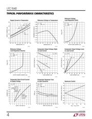
Nanopower Comparator
with Reference
V
+
R1
4.32M
1%
R2
3M
1%
3.3V
V
–
21
7
8
GND
OUT
LTC1540
1540 • TA01
IN
+
IN
–
HYST
REF
3
4
5
6
–
+
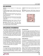
TEMPERATURE (°C)
–40
0.50
0.45
0.40
0.35
0.30
0.25
0.20
0.15
20 60
1540 • TA02
–20 0
40 80 100
SUPPLY CURRENT (µA)
V
+
= 5V
V
–
= GND = 0V
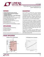
The LTC
®
1540 is an ultralow power, single comparator
with built-in reference. The comparator’s features
include less than 0.6µA supply current over the commer-
cial temperature range, a 1.182V ±2% reference, pro-
grammable hysteresis and TTL/CMOS outputs that sink
and source current. The reference output can drive a
bypass capacitor of up to 0.01µF without oscillation.
The comparator operates from a single 2V to 11V supply
or a dual ±1V to ±5.5V supply. Comparator hysteresis is
easily programmed by using two resistors and the HYST
pin. Each comparator’s input operates from the negative
supply to within 1.3V of the positive supply. The compara-
tor output stage can continuously source up to 40mA. By
eliminating the cross-conducting current that normally
occur when the comparator changes logic states, power
supply glitches are eliminated.
The LTC1540 is available in the 8-pin MSOP and SO
packages. For space limited applications, the LTC1540 is
available in a 3mm x 3mm low profile (0.8mm) dual fine-
pitch leadless package (DFN).
Nanopower 2.9V V
CC
Threshold Detector
LTC1540 Supply Current vs Temperature
■
Ultralow Quiescent Current: 0.3
µ
A Typ
■
Reference Output Drives 0.01
µ
F Capacitor
■
Adjustable Hysteresis
■
Available in 3mm x 3mm x 0.8mm DFN Package
■
Wide Supply Range: 2V to 11V
■
Input Voltage Range Includes the Negative Supply
■
Reference Output Sources Up to 1mA
■
TTL/CMOS Compatible Outputs
■
60µs Propagation Delay with 10mV Overdrive
■
No Crowbar Current
■
40mA Continuous Source Current
■
Pin Compatible with LTC1440, MAX921, MAX931
, LTC and LT are registered trademarks of Linear Technology Corporation.
■
Battery-Powered System Monitoring
■
Threshold Detectors
■
Window Comparators
■
Oscillator Circuits
Verzeichnis
- ・ Konfiguration des Pinbelegungsdiagramms on Seite 5
- ・ Abmessungen des Paketumrisses on Seite 10
- ・ Paket-Footprint-Pad-Layout on Seite 10 Seite 11
- ・ Typisches Anwendungsschaltbild on Seite 7 Seite 8 Seite 9 Seite 12
- ・ Technische Daten on Seite 3
- ・ Anwendungsbereich on Seite 5 Seite 6 Seite 7 Seite 8 Seite 9
- ・ Elektrische Spezifikation on Seite 3 Seite 4