
herunterladen

User's Guide
SLVUA04–February 2014
LMZ31710 Parallel User's Guide
The LMZ31710 device is a 2.95-V to 17-V input, 10-A output, Simple Switcher™ power module, which
integrates the PWM controller, power MOSFETs, shielded inductor, and passives in a low-profile, QFN
package. For applications requiring greater than 10 A, it is possible to parallel up to six LMZ31710
devices. This user's guide provides information on the correct usage of the test board and an explanation
of the test points and jumpers on the board.
Contents
1 Description ................................................................................................................... 2
2 Getting Started .............................................................................................................. 2
3 Test Point Descriptions ..................................................................................................... 4
4 Operation Notes ............................................................................................................. 4
5 Current Limitations .......................................................................................................... 5
6 Performance Data ........................................................................................................... 6
7 2× Parallel Bill of Material ................................................................................................ 11
8 2× Parallel Schematic ..................................................................................................... 12
9 4× Parallel Bill of Material ................................................................................................ 14
10 4× Parallel Schematic ..................................................................................................... 15
List of Figures
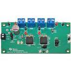
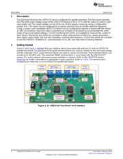
1 2× LMZ31710 Test Board User Interface................................................................................ 2
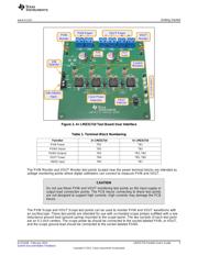
2 4× LMZ31710 Test Board User Interface................................................................................ 3
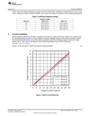
3 Typical Current Balancing ................................................................................................. 5
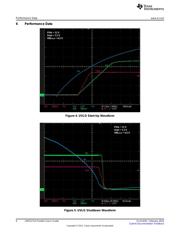
4 UVLO Start-Up Waveform ................................................................................................. 6
5 UVLO Shutdown Waveform ............................................................................................... 6
6 INH Start-Up Waveform.................................................................................................... 7
7 INH Shutdown Waveform.................................................................................................. 7
8 Output Voltage Ripple – In-Phase........................................................................................ 8
9 Output Voltage Ripple – 180° Out-of-Phase ............................................................................ 8
10 Input Voltage Ripple – In-Phase .......................................................................................... 9
11 Input Voltage Ripple – 180° Out-of-Phase .............................................................................. 9
12 Transient Response – 10-A Load Step (1 A/µs) ...................................................................... 10
List of Tables
1 Terminal Block Numbering................................................................................................. 3
2 Switching Frequency Range............................................................................................... 5
1
SLVUA04–February 2014 LMZ31710 Parallel User's Guide
Submit Documentation Feedback
Copyright © 2014, Texas Instruments Incorporated
Verzeichnis