
herunterladen
User's Guide
SNVA226C–February 2007–Revised April 2013
AN-1596 LM5116 Evaluation Board
1 Introduction
The LM5116 evaluation board is designed to provide the design engineer with a fully functional power
converter based on emulated current mode control to evaluate the LM5116 controller IC. The evaluation
board provides a 5V output with a 7A current capability. The wide input voltage ranges from 7V to 60V.
The design operates at 250kHz, a good compromise between conversion efficiency and solution size. The
printed circuit board consists of 4 layers, 2 ounce copper top and bottom, 1 ounce copper internal layers
on FR4 material with a thickness of 0.06 inches. This application note contains the evaluation board
schematic, Bill-of-Materials (BOM) and a quick setup procedure. Refer to the LM5116 Wide Range
Synchronous Buck Controller (SNVS499) data sheet for complete circuit design information.
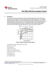
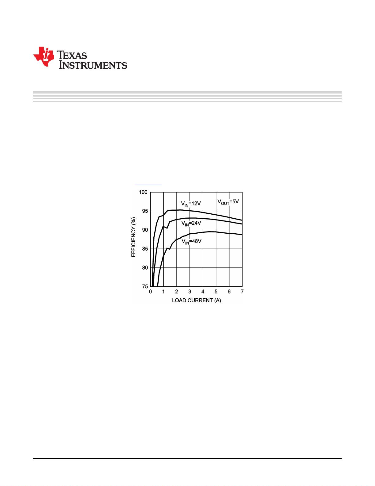
Figure 1. Efficiency with 6 µH Cooper Inductor
The performance of the evaluation board is as follows:
Input Range: 7V to 60V
Output Voltage: 5V
Output Current: 0 to 7A
Frequency of Operation: 250 kHz
Board Size: 2.55 X 2.65 X 0.5 inches
Load Regulation: 1%
Line Regulation: 0.1%
Over Current Limiting
All trademarks are the property of their respective owners.
1
SNVA226C–February 2007–Revised April 2013 AN-1596 LM5116 Evaluation Board
Submit Documentation Feedback
Copyright © 2007–2013, Texas Instruments Incorporated
Verzeichnis
- ・ Blockdiagramm on Seite 8
- ・ Anwendungsbereich on Seite 13