
herunterladen
User's Guide
SNVA222A–March 2007–Revised April 2013
AN-1590 LM3405 Demo Board
1 Introduction
The LM3405 demo board is configured to drive a series string of high power, high brightness LEDs at a
forward current of 1A using the LM3405 constant current buck regulator. The board can accept a full input
operating range of 3V to 15V. The converter output voltage adjusts as needed to maintain a constant
current through the LED array. The LM3405 is a step-down regulator with an output voltage range
extending from a V
O(MIN)
of 205mV (the reference voltage) to a V
O(MAX)
determined by the maximum duty
cycle (typically 94%). It can drive up to 3 LEDs in series at 1A forward current, with the single LED forward
voltage of approximately 3.7V (Typical of white, blue, and green LEDs using InGaN technology).
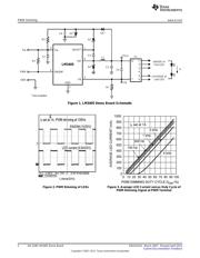
As shown in the demo board schematic circuit in Figure 1, the board is configured with the boost voltage
derived from V
IN
through a shunt zener (D3). This will ensure that the gate drive voltage V
BOOST
- V
SW
falls
in the recommended range of 2.5V to 5.5V when V
IN
varies from 5V to 15V. In cases of low input voltages
(3V to 5V) being used, the boost diode (D2) can be directly connected to V
IN
(R3 short, C4 and D3 not
installed) to obtain sufficient gate drive voltage for best performance.
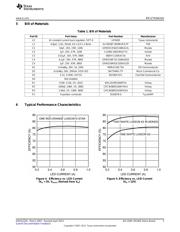
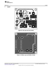
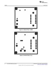
Table 1 lists the bill of materials of this demo board. The measured performance characteristics and layout
of this board are also included below. Additional Circuit Configuration Schematics section illustrates other
possible circuit configurations of this board to accommodate various input and output requirements as
discussed in the LM3405 datasheet.
2 Connecting to LED Array
The LM3405 Demo Board includes a female 6-position SIP connector P1 as well as two standard 72mil
turret connectors for the cathode and anode connections of the LED array. Solid 18 or 20 gauge wire with
about 1cm of insulation stripped away makes a convenient, solderless connection to P1.
3 Setting the LED Current
The default forward current I
F
delivered to the LED array is 1.0A. To adjust this value the current setting
resistor R1 can be changed according to the following equation:
I
F
= V
FB
/ R1 (1)
The feedback voltage V
FB
is regulated at 0.205V typically. The resistor R1 should be rated to handle the
power dissipation of the LED current. R1 should be less than approximately 1Ω, to ensure that the LED
current is kept above 200mA. If average LED currents of less than 200mA are desired, the EN/DIM pin
should be used for PWM dimming.
4 PWM Dimming
The default connection of the PWM terminal is tied to V
IN
through a 100kΩ resistor (R2) to enable the chip,
which allows the set current to flow through the LEDs continuously. This PWM terminal can also be
connected separately to a periodic pulse signal at different frequencies and/or duty cycle for PWM
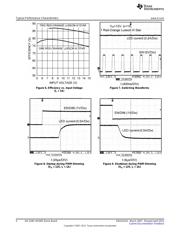
dimming. A typical LED current waveform in PWM dimming mode is shown in Figure 2. Figure 3 shows
the average LED current versus duty cycle of PWM dimming signal for various frequencies. Due to an
approximately 100µs delay between the dimming signal and LED current, the dimming ratio reduces
dramatically if the applied PWM dimming frequency is greater than 5kHz.
All trademarks are the property of their respective owners.
1
SNVA222A–March 2007–Revised April 2013 AN-1590 LM3405 Demo Board
Submit Documentation Feedback
Copyright © 2007–2013, Texas Instruments Incorporated
Verzeichnis