
herunterladen
F
S
=
V
OUT
1.42 x 10
-10
x
R1
t
ON
=
V
IN
1.42 x 10
-10
x
R1
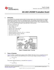
User's Guide
SNVA152A–March 2006–Revised April 2013
AN-1453 LM25007 Evaluation Board
1 Introduction
The LM25007EVAL evaluation board provides the design engineer with a fully functional buck regulator,
employing the constant on-time (COT) operating principle. This evaluation board provides a 5V output
over an input range of 9V - 42V. The circuit delivers load currents to 450 mA, with current limit at ≊670
mA. The board is populated with all external components except C6 and C9. These components provide
options for managing the output ripple as described later in this document.
The board’s specification are:
• Input Voltage: 9V to 42V
• Output Voltage: 5V
• Maximum load current: 450 mA
• Minimum load current: 0 mA
• Current Limit: ≊670 mA
• Measured Efficiency: 92.6% (V
IN
= 9V, I
OUT
= 150 mA)
• Nominal Switching Frequency: 306 kHz
• Size: 1.6 in. x 1.0 in. x 0.5 in
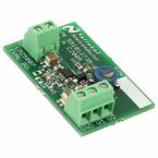
Figure 1. Evaluation Board - Top Side
2 Theory of Operation
Figure 5 contains a simplified block diagram of the LM25007. When the circuit is in regulation, the buck
switch is on each cycle for a time determined by R1 and the input voltage according to Equation 1:
(1)
The nominal switching frequency is calculated from Equation 2:
(2)
All trademarks are the property of their respective owners.
1
SNVA152A–March 2006–Revised April 2013 AN-1453 LM25007 Evaluation Board
Submit Documentation Feedback
Copyright © 2006–2013, Texas Instruments Incorporated
Verzeichnis
- ・ Blockdiagramm on Seite 5
- ・ Anwendungsbereich on Seite 10