

herunterladen

AN-111
General PCB Design and Layout Guidelines
Micrel 10/100 Switches and PHYs
Micrel Inc. • 2180 Fortune Drive • San Jose, CA 95131 • USA • tel +1 (
408
) 944-0800 • fax + 1 (408) 474-1000 • http://www.micrel.com
February 2007
M9999-020907-1.1
Introduction
This application note is intended to assist customers in
designing products that comply with both EMI and ESD
standards using Micrel’s 10/100 family of Ethernet
products.
The printed circuit board (PCB) is the single most
important factor that affects EMI, ESD and overall
performance. In order to meet these requirements depend
on good design practices. The goal here is to minimize
digital and common mode noise as well as to provide
shielding between the PCB’s internal circuitry and the
external environment. These PCB design practices should
apply to the entire PCB design, not just to Micrel Ethernet
products.
All datasheets and support documentation can be found
on Micrel’s web site at: www.micrel.com
.
General Rules
• Place components so as to avoid long loop traces.
• Choose a metal box to shield the printed circuit
board.
• Use a ferrite core on the DC power cord to reduce
EMI.
• Follow the guidelines to layout differential pairs,
the ground plane, and high-speed signals.
• Provide controlled impedance on all clock lines
and high-speed digital signals traces with right
termination schemes to prevent reflection and
ringing.
• Ensure that the power supply is rated for the
application and optimized with decoupling
capacitors.
• Keep power and ground noise under 50mV peak-
to-peak.
• Ensure that the switching DC-DC converter is
filtered and properly shielded as the DC-DC power
converter can produce a great deal of EMI noise.
• Avoid via and pad in the path on any critical signal
as via and pad will induce unwanted capacitance
and inductance which can cause reflection and
distortion.
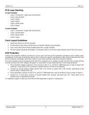
Power Ground Rules
• Do not split the ground plane into separate planes
for analog, digital, power pins. A single and
contiguous ground plane is recommended.
• Route high-speed signals above a solid and
unbroken ground plane.
• Fill copper in the unused area of signal planes and
connect these coppers to the ground plane
through vias.
• Stagger the placement of vias to avoid creating
long gap in the plane due to via voids.
Analog VCC Plane
Place and route analog components within the Analog
VCC plane.
Digital VCC plane
Place and route digital components within the Digital VCC
plane.
Signal Ground
The signal ground region should be one continuous and
unbroken plane. Both analog (AGND) and digital (DGND)
grounds should be directly connected to the signal ground
plane.
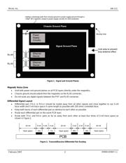
Chassis Ground
The chassis ground and magnetics serve two purposes:
they help to reduce EMI noise emissions from the signal
ground plane to the PCB’s external environment and also
act as a shield to protect the PCB components from ESD.
Place the chassis ground on all PCB layers and use
connection mounting holes to join the chassis ground on
different PCB layers
This chassis ground on the PCB is directly connected to
the metal shield of equipment through the connection
mounting holes.
Use a trench/moat to isolate the chassis ground plane
from the signal ground plane.
The chassis ground region extends from the front edge of
the PCB board (RJ45 connectors) to the magnetics and
around the edge of the board as shown in Figure 1.