
herunterladen

User's Guide
SBAU220–February 2014
INA300EVM User's Guide
This user’s guide describes the INA300 evaluation module (EVM). This document discusses the set-up
and operating instructions, schematic, printed circuit board (PCB) design, and bill of materials. Throughout
this document, the abbreviation EVM and the term evaluation module are synonymous with the
INA300EVM.
Contents
1 Overview ..................................................................................................................... 2
List of Figures
1 INA300EVM Overview...................................................................................................... 3
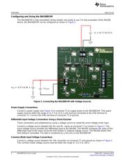
2 Connecting the INA300EVM with Voltage Sources .................................................................... 4
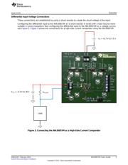
3 Connecting the INA300EVM as a High-Side Current Comparator ................................................... 5
4 Enable/Disable Jumper Location.......................................................................................... 7
5 Enable/Disable Schematic Connections ................................................................................. 7
6 Transparent/Latch Jumper................................................................................................. 8
7 Transparent/Latch Schematic Connections ............................................................................. 8
8 Delay Jumper Location..................................................................................................... 9
9 Delay Schematic Connections ............................................................................................ 9
10 Hysteresis Jumper Location.............................................................................................. 10
11 Hysteresis Schematic Connections ..................................................................................... 10
12 Limit Jumper Location .................................................................................................... 11
13 Limit Schematic Connections............................................................................................ 11
14 Low-Pass, Passive Input Filter .......................................................................................... 12
15 INA300EVM Schematic................................................................................................... 13
16 INA300EVM Top Overlay................................................................................................. 14
17 INA300EVM Top Solder Mask........................................................................................... 14
18 INA300EVM Top Layer ................................................................................................... 14
19 INA300EVM Bottom Layer ............................................................................................... 14
20 INA300EVM Bottom Solder Mask....................................................................................... 15
21 INA300EVM Drill Drawing................................................................................................ 15
22 INA300EVM Board Dimensions ......................................................................................... 15
All trademarks are the property of their respective owners.
1
SBAU220–February 2014 INA300EVM User's Guide
Submit Documentation Feedback
Copyright © 2014, Texas Instruments Incorporated
Verzeichnis