
herunterladen
User's Guide
SLVUA58–April 2014
DRV8307 User’s Guide
This document is provided with the DRV8307 customer evaluation module (EVM) as a supplement to the
DRV8307 datasheet (SLVSCK2). It details the hardware implementation of the EVM.
Contents
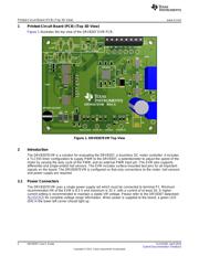
1 Printed-Circuit Board (PCB) (Top 3D View).............................................................................. 2
2 Introduction ................................................................................................................... 2
2.1 Power Connectors.................................................................................................. 2
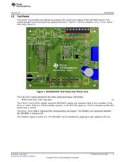
2.2 Test Points........................................................................................................... 3
2.3 Jumpers.............................................................................................................. 4
2.4 SPEED ADJUSTMENT (JP6) Jumper and (R20) Potentiometer............................................. 7
2.5 Operation of the EVM .............................................................................................. 8
3 Schematic and Bill of Materials ............................................................................................ 9
List of Figures
1 DRV8307EVM Top View.................................................................................................... 2
2 DRV8307EVM Test Points and FAULTn LED ........................................................................... 3
3 DRV8308EVM Jumpers..................................................................................................... 4
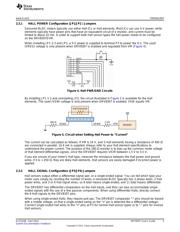
4 Hall PWR/GND Circuits..................................................................................................... 5
5 Circuit when Setting Hall Power to “Current”............................................................................. 5
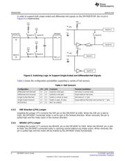
6 Switching Logic to Support Single-Ended and Differential-Hall Signals.............................................. 6
7 SPEED Adjustment Configuration......................................................................................... 7
8 DRV8307EVM Schematic .................................................................................................. 9
List of Tables
1 Jumper Descriptions......................................................................................................... 4
2 Hall Sensors.................................................................................................................. 6
3 DRV8307EVM Bill of Materials........................................................................................... 10
1
SLVUA58–April 2014 DRV8307 User’s Guide
Submit Documentation Feedback
Copyright © 2014, Texas Instruments Incorporated
Verzeichnis