

herunterladen

QUICK START GUIDE FOR DEMONSTRATION CIRCUIT 910A
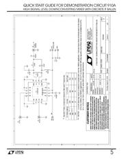
HIGH SIGNAL LEVEL DOWNCONVERTING MIXER WITH DISCRETE IF BALUN
1
LT5557
DESCRIPTION
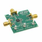
Demonstration circuit 910A is optimized for evaluation
of the LT5557 active downconverting mixer with dis-
crete IF output balun for lower cost applications. Its
RF input and LO input ports are internally matched to
50
Ω
ΩΩ
Ω
, from 1.6 to 2.3GHz, and from 1 to 5GHz, respec-
tively. The IF output is 50
Ω
ΩΩ
Ω
matched to 240MHz using
a discrete balun. Compared to the transformer-based
matching technique, the discrete balun approach yields
narrower IF output bandwidth, higher conversion gain,
and slightly degraded IIP3 and noise figure.
The LT5557 active mixer is optimized for high linearity,
wide dynamic range downconverter applications. The
IC includes a high-speed differential LO buffer amplifier
driving a double-balanced mixer. Broadband, inte-
grated transformers on the RF and LO inputs provide
single-ended 50Ω
ΩΩ
Ω interfaces. The differential IF output
allows convenient interfacing to differential IF filters
and amplifiers, or is easily matched to drive a single-
ended 50Ω
ΩΩ
Ω load, with or without an external trans-
former.
The LT5557’s high level of integration minimizes the
total solution cost, board space and system-level varia-
tion.
Design files for this circuit board are available. Call
the LTC factory.
, LT, LTC, and LM are registered trademarks of Linear Technology Corporation.
Table 1.
Typical Demonstration Circuit Performance Summary (V
CC
= 3.3V, EN = High, T
A
= 25°C, f
RF
= 1950MHz, P
RF
= -6dBm, f
LO
=
1710MHz, P
LO
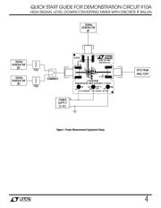
= -3dBm, IF output measured at 240MHz, unless otherwise noted. Test circuit shown in Figure 2.)
PARAMETER CONDITION VALUE
Supply Voltage 2.9 to 3.9V
Total Supply Current EN = High (> 2.7V) 81.6mA
Maximum Shutdown Current EN = Low (< 0.3V) 100µA
RF Input Frequency Range Return Loss > 12dB 1600 to 2300MHz
LO Input Frequency Range Return Loss > 10dB 1000 to 4200MHz
IF Output Frequency Range Return Loss > 10dB 220 to 260MHz
LO Input Power
-8 to 2dBm
Conversion Gain 2.9dB
Input 3
rd
Order Intercept 2 RF tones, -6dBm/tone, ∆f = 1MHz 24.7dBm
Single-Sideband Noise Figure 11.7dB
LO to RF Leakage < -45dBm
LO to IF Leakage < -42dBm
RF to LO isolation > 42dB
RF to IF isolation > 41dB
2RF-2LO Output Spurious Product
(f
RF
= f
LO
± f
IF
/2)
F
RF
= 1830MHz, P
RF
= -6dBm, f
IF
= 240MHz
-53dBc
3RF-3LO Output Spurious Product
(f
RF
= f
LO
± f
IF
/3)
F
RF
= 1790MHz, P
RF
= -6dBm, f
IF
= 240MHz
-70dBc
Input 1dB Compression 8.8dBm