
herunterladen
Semiconductor Components Industries, LLC, 2012
January, 2012 − Rev. 1
1 Publication Order Number:
EVBUM2054/D
CS5171BSTEVB
CS5171/3 3.3 V to 5.0 V/
400 mA Boost Regulator
Evaluation Board User's
Manual
Description
The CS5171/3 demo board is configured as a compact, low
profile and efficient boost regulator. This board allows initial
evaluation of the performance of the CS5171 (260 kHz) or
the CS5173 (520 kHz) 1.5 A boost regulator IC. The
demonstration circuit converts 3.3 V to 5.0 V with a
maximum load current of 400 mA.
The high integration level of the CS5171 minimizes the
external component count to 10. A high-frequency oscillator
built into CS5171 allows the use of all surface mount
components, greatly reducing the size and height of the
circuit. Using a TTL-compatible pulse train, one can
increase and synchronize the switching frequency to almost
twice the built-in frequency.
This regulator can also be put into a sleep mode. The 5.0 V
output is disabled and the circuit consumes minimum
current. The inherent protection features of the CS5171
ensure that the power supply can survive power-on and
heavy load conditions.
Features
Current Mode Control with Pulse-By-Pulse Current
Limit
Easy External Sync Function
Power Down Mode Consuming Maximum 50 mA
Small Board Space Requiring Only 0.7 0.7 in.
2
Low Profile with Component Height Less Than 0.1 in.
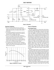
High Energy Transfer Efficiency
Excellent Line and Load Regulation
Fast Transient Response
Minimum Output Voltage Ripple
High Reliability with All Ceramic Capacitors
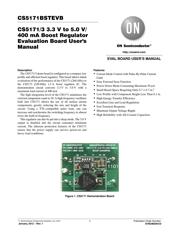
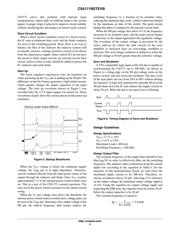
Figure 1. CS5171 Demonstration Board
http://onsemi.com
EVAL BOARD USER’S MANUAL
Verzeichnis