

herunterladen
SWRU300
August
2011
Web sites:
www.ti.com/lprf
E2E Forum:
www.ti.com/lprf
-
forum
Make sure to subscribe to the Low
-
Power RF
Newsletter to receive information about updates to
documentation, new product releases
,
and more.
Sign up on the TI web pages.
CC
2540
Development Kit
Quick Start
Guide
Opening the B
ox an
d R
unning the
Bluetooth
®
Low Energy
SimpleBLE
Demo Application
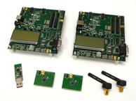
1. Kit Contents
2
x
SmartRF
05EB (the two large boards)
2 x CC
2540 Evaluation Mod
u
les
2 x
Pulse A
ntennas
1 x
CC2540 USB Dongle
Cables
Documentation
Please contact a TI Representative if any parts
are missing from the kit.
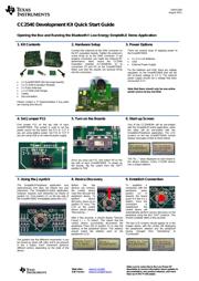
2.
Hardware Setup
Connect the antennas to the SMA connector on
the RF evaluation boards. Tighten the antenna’s
screw firmly on to the
SMA connector. If not
properly connected, you might see reduced RF
performance. Next, mount the
CC2540
evaluation modules (
CC2540
EMs) on to
connectors P5 and P6 on the SmartRF05EB.
Make sure that the boards are pressed firmly
into the connectors.
3.
P
ower Options
There are several ways of applying power to
the
SmartRF05
EB.
2 x 1.5 V AA
B
atteries
USB
External Power Supply
For the batteries and USB, there are voltage
regulators on the
SmartRF05EB
that will set
the on
-
board voltage to 3.3 V. The extern
al
power supply should set a voltage that does
no
t exceed 3.3 V.
Note that there should only be one active
power source at any one time.
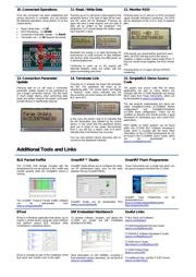
4. Se
t
Jumper P11
Find jumper P11 on the top side of each
SmartRF05EB. This jumper is used to set the
power sourc
e for the board. Set P11 to “1
-
2” if
you are using battery power. Set P11 to “2
-
3” if
you are using USB or an external power supply.
5
.
Turn on the Boards
Once you have set P11, find switch P8 on the
top side
of each SmartRF05EB. To power up
the boards, flip the switch from the “OFF”
position to “ON”
6
.
Start
-
up Screen
One of the CC2540
EMs
will be pre
-
loaded
with the SimpleBLECentral application, while
the other will be pre
-
loaded with the
SimpleBLEPeripheral
application. The LCD
screens on the two SmartRF05EBs should
display message
s
similar to those below:
The “0x…” value displayed on each board is
the device address. Every CC2540 dev
ice
has
a unique address.
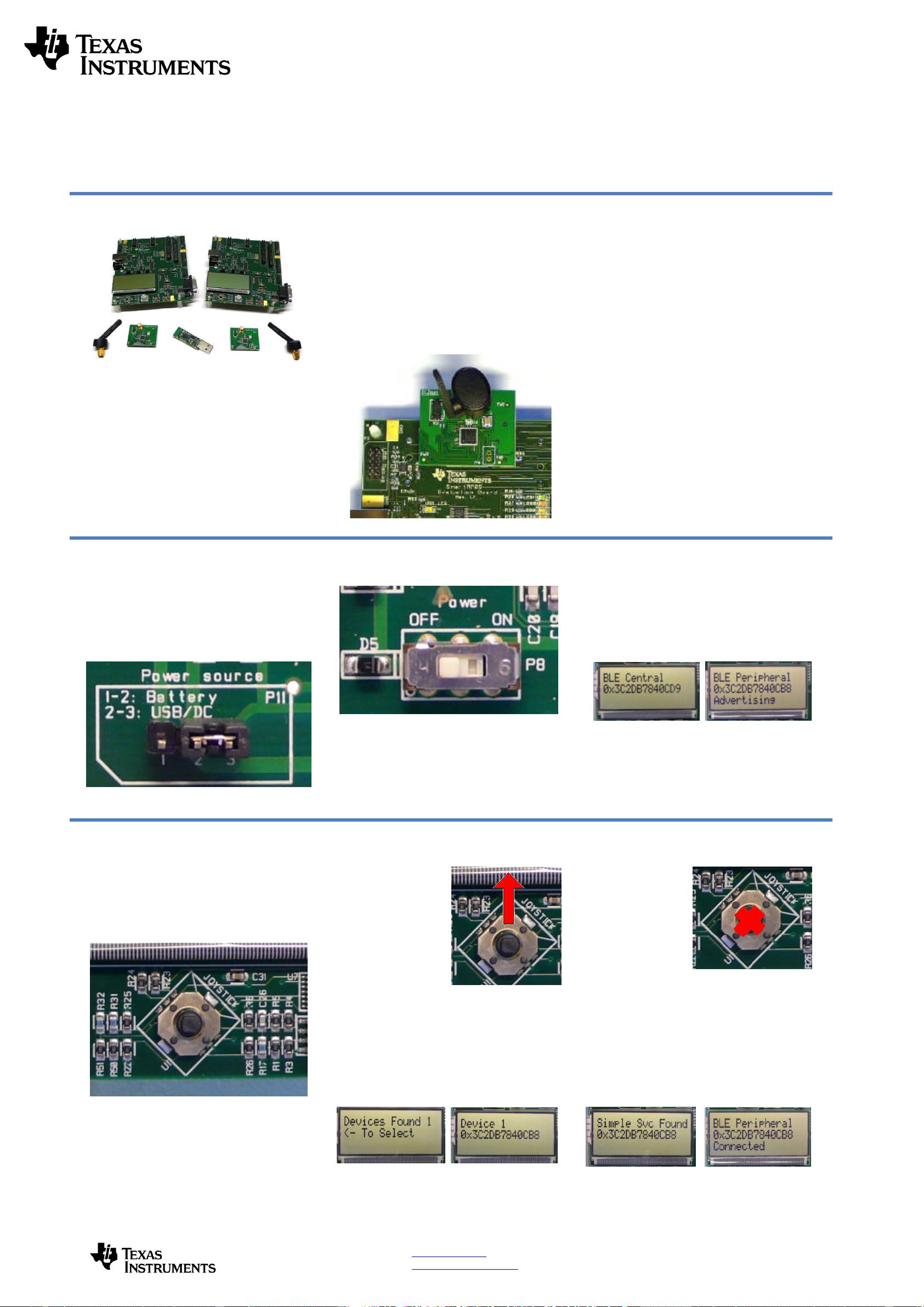
7
.
Us
ing the Joystick
The SimpleBLEPeripheral application runs
autonomously and does not require any user
interaction. The SimpleBLECentral application,
however,
requires user interaction by means of
joystick U1. Find joystick U1 on the top side of
the SmartRF
05EB, immediately below the LCD.
The joystick has five different movements: it can
be moved up, down, left, right, and it can pressed
in like a button. Each movement performs
different actions depending on the state of the
device.
8
.
Device Discovery
Before the two
devices can connect,
the central device
must first discover the
peripheral device. To
perform device
discovery, press up on
joystick U1 once. The
LCD on the central
device should display
“Discovering…”.
After a few seco
nds, it should display “Devices
Found 1 / <
-
To Select”. This means that the
central device successfully discovered the
peripheral. Press left on joystick U1 to view the
address of the peripheral device. This address
should match the address seen on the
pe
ripheral’s LCD.
9
.
Establish Connection
To establish a
connection with the
peripheral, press
joystick U1 in
towards the board
(push it in like it is a
button). Once the
connection is
established, the
central devi
ce will
automatically perform service discovery on the
peripheral using the
BLE
GATT protocol. This
should complete within a few
seconds.
The two LCD screens should appear as in the
images below, with the central still displaying
the peripheral’s address
and the peripheral
having changed from “Advertising” to
“Connected”: