
herunterladen
SWRU284A
October 2015
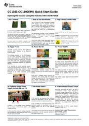
CC1101-CC1190EMK Quick Start Guide
Opening the box and using the modules with SmartRF04EB
1. Kit Contents
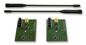
2 x CC1101-CC1190EM (869 or 915 MHz)
2 x Pulse W5017 Antennas (2 dBi)
The 869 MHz RF boards are designed to comply with
relevant ETSI regulatory requirements over temperatures
from 0 to +35°C. The 915 MHz RF boards are designed
to comply with relevant FCC and IC regulatory
requirements over temperatures from 0 to +35°C.
The boards should not be modified to operate in other
frequency bands than what they have been designed for.
2. How to Use the Modules
The CC1101-CC1190 Evaluation Module
(EM) boards can be plugged into the
SmartRF04EB (EB), which is included in
the CC1101DK. This board lets you control
the devices from SmartRF™ Studio and it
can also be used as a development
platform.
The evaluation module is also supported
by the SmartRF TrxEB, included in the
CC11xL, CC1120 and CC1200
development kits.
This Quick Start Guide describes how to
properly power the SmartRF04EB with a
CC1101-CC1190EM and how to control
the combo from SmartRF Studio.
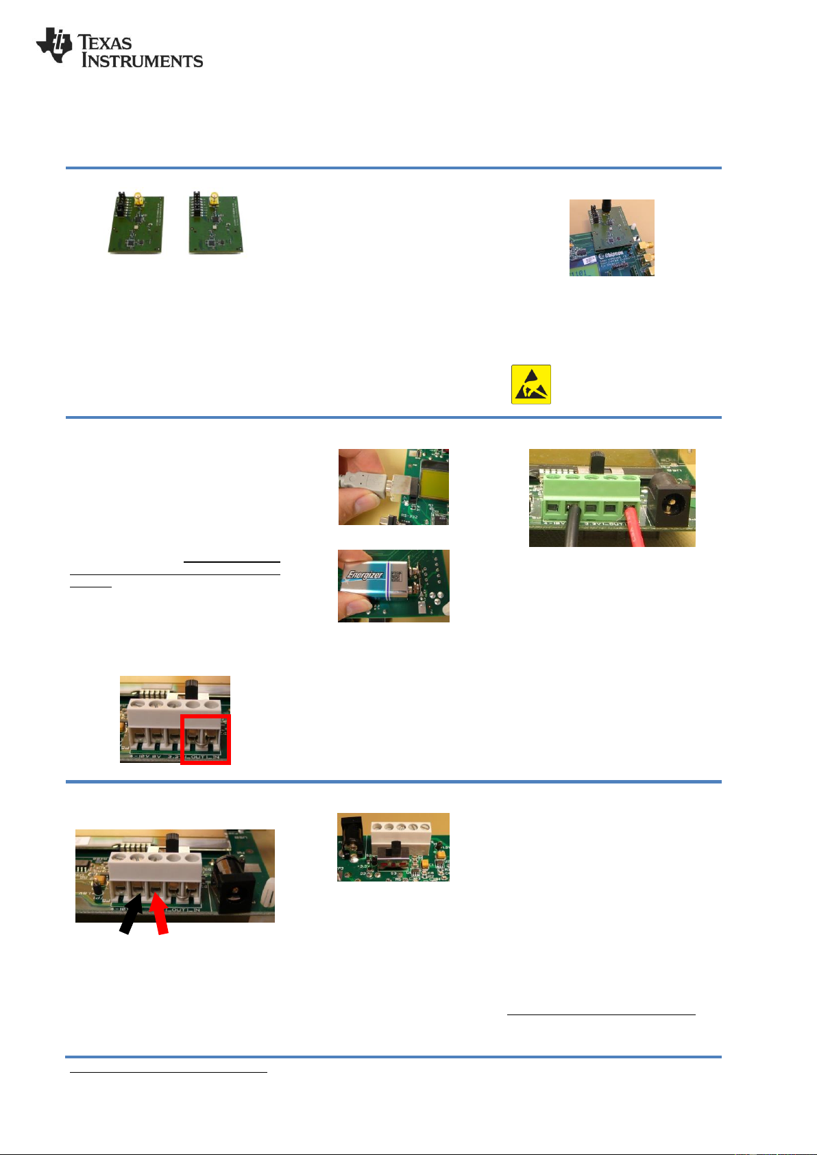
3. Plug EM into SmartRF04EB
Insert the EM into the EB. Attach the antenna
firmly.
Caution! Due to potential high output power from
the device, please keep a distance of at least 20
cm between the user and the antenna.
Caution! The kit contains ESD sensitive
components. Handle with care to prevent
permanent damage.
4a. Apply Power
The EB can be powered from different
sources: USB, Battery or an External
Power Supply
The voltage regulator on the EB supplies
3.3 V to the assembly, but it can only
source up to 150 mA. It cannot supply the
CC1101-CC1190EM since it can consume
more than 300 mA. An external power
supply is therefore required for powering
the EM.
1
It is possible to have separate power
sources for the EB and for the EM. This is
controlled with the strap between I_OUT
and I_IN on P5 (the screw terminal).
Remove it to allow separate power
supplies.
4b. Power the EB
Connect the EB to a USB port on a PC.
Alternatively, connect a 9 Volt, non-
rechargeable, alkaline battery to the
battery connector on the bottom side of the
board.
Note that if multiple power sources are
connected, the source with the highest
voltage will power the EB. This means that
you should disconnect any attached
battery when using USB power; otherwise
the battery will be drained.
4c. Power the EM
As noted in 4a, remove the strap on P5
and connect the external power supply as
shown in the picture above. The red wire is
the positive supply and the black wire is
GND.
This will power the EM directly from the
external power supply, whereas the rest of
the EB will be powered from USB or the
battery.
The power supply range should be within
3.0 to 3.6 V.
4d. Optional: Same Power
Supply for both EB and EM
Connect a 3.3 V voltage source between
the 3.3 V and 0 V terminals. 3.3 V is the
middle terminal.
In this case, the on-board voltage regulator
will be bypassed. Note that the strap on P5
should not be removed.
5. Set Power Switch
If EB and EM are powered from different
sources as described in 4a-4c, the switch
should be set to the rightmost position.
If EB and EM are powered from the same
external supply as described in 4d, the
switch should be set to the leftmost
position.
This switch can be used to turn off the EB
by switching it to the opposite position of
that used to turn it on.
6. External Power Supply Range
With the test setup in 4a-4c, the EB is
connected to a 3.3 V supply through the
on-board voltage regulator and the EM is
powered by the external supply. Since the
EB is powered through a regulated 3.3 V
supply the signals going from CC1101-
CC1190 to the EB (and vice versa) need to
be within 3.0 V to 3.6 V. The external
supply connected to the EM when using
the setup in 4a-4c is therefore limited to 3.0
V to 3.6 V.
With the setup in 4d the supply range is
limited 2.7 V to 3.6 V.
External Power Supply
2
Requirements:
Nom Voltage: 3.3VDC
Max Current: 800 mA
Efficiency Level V
1
Note that this is not the case for the SmartRFTrxEB.
2
When using an external power supply, make sure it meets the listed requirements in addition to complying with applicable regional product regulatory and safety certification
requirements such as UL, CSA, VDE, CCC, and PSE
GND
VDD