
herunterladen

User's Guide
SLUUAA8A–September 2013–Revised August 2014
User's Guide for bq25505 Battery Charger Evaluation
Module for Energy Harvesting
This user’s guide describes the bq25505 evaluation module (EVM), how to perform a stand-alone
evaluation and how to allow the EVM to interface with the system and host. The boost charger output is
configured to deliver up to 4.2-V maximum voltage to its output, VSTOR, using external resistors. This
voltage is applied to the storage element as long as the storage element voltage at VBAT_SEC is above
the internally programmed undervoltage of 2 V. The VBAT_OK indicator toggles high when VSTOR ramps
up to 3 V and toggles low when VSTOR ramps down to 2.8 V.
Contents
1 Introduction ................................................................................................................... 2
1.1 EVM Features....................................................................................................... 2
1.2 General Description ................................................................................................ 2
1.3 Design and Evaluation Considerations .......................................................................... 3
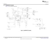
1.4 bq25505EVM Schematic........................................................................................... 4
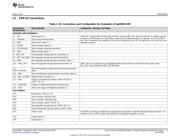
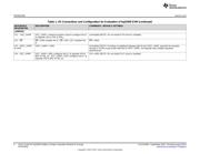
1.5 EVM I/O Connections .............................................................................................. 5
2 EVM Performance Specification Summary............................................................................... 7
3 Test and Measurement Summary......................................................................................... 7
3.1 Test Setups and Results........................................................................................... 8
4 Bill of Materials and Board Layout ....................................................................................... 15
4.1 Bill of Materials .................................................................................................... 15
4.2 EVM Board Layout................................................................................................ 16
5 PCB Layout Guideline ..................................................................................................... 20
List of Figures
1 bq25505EVM Schematic.................................................................................................... 4
2 Test Setup for Measuring Boost Charger Efficiency .................................................................... 9
3 Charger Efficiency versus Input Voltage.................................................................................. 9
4 Charger Efficiency versus Input Current ................................................................................ 10
5 Test Setup for Measuring Charger Operation .......................................................................... 11
6 Charger Operational Waveforms During Battery Charging........................................................... 11
7 Test Setup................................................................................................................... 12
8 Switching from Primary to Secondary Battery.......................................................................... 13
9 Test Setup for Charging a Super Capacitor on VBAT_SEC.......................................................... 13
10 Charging a Super Cap on VBAT_SEC ................................................................................. 14
11 EVM PCB Top Silk......................................................................................................... 16
12 EVM PCB Top Assembly.................................................................................................. 17
13 EVM PCB Top Layer ...................................................................................................... 18
14 EVM PCB Bottom Layer................................................................................................... 19
List of Tables
1 I/O Connections and Configuration for Evaluation of bq25505 EVM ................................................. 5
2 Bill of Materials ............................................................................................................. 15
1
SLUUAA8A–September 2013–Revised August 2014 User's Guide for bq25505 Battery Charger Evaluation Module for Energy
Harvesting
Submit Documentation Feedback
Copyright © 2013–2014, Texas Instruments Incorporated
Verzeichnis
- ・ Blockdiagramm on Seite 4
- ・ Beschreibung der Funktionen on Seite 2
- ・ Technische Daten on Seite 7
- ・ Anwendungsbereich on Seite 21 Seite 24