


herunterladen
www.advancedpower.com 1/12
Application note
1903
JULY 2006
www.microsemi.com
Advanced IGBT Driver
APPLICATION MANUAL
Alain Calmels
Product Engineer (Power Modules)
Microsemi® Power Module Products
33700 Merignac, France
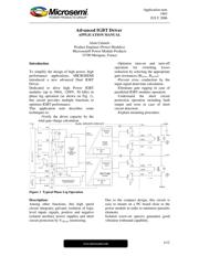
Introduction
To simplify the design of high power, high
performance applications, MICROSEMI
introduced a new advanced Dual IGBT
Driver.
Dedicated to drive high Power IGBT
modules (up to 300A, 1200V, 50 kHz) in
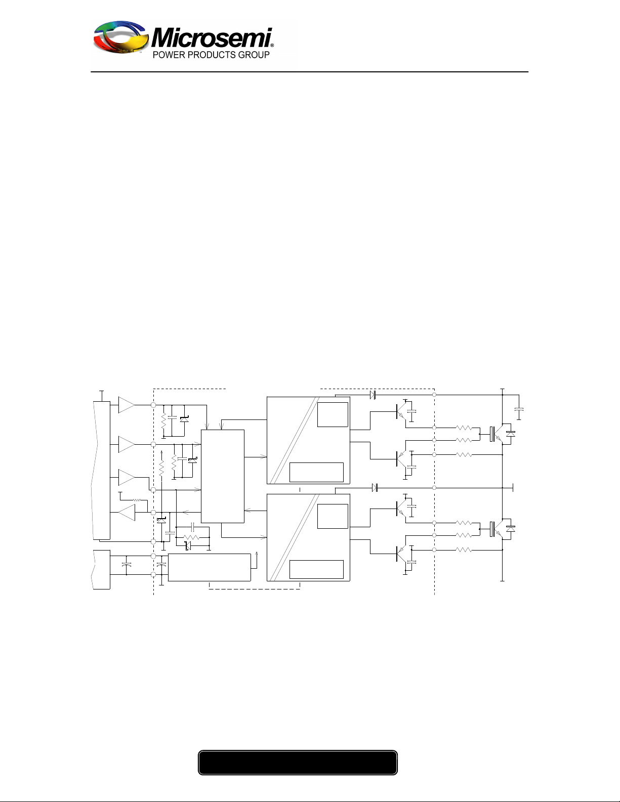
phase leg operation (as shown on Fig. 1),
this circuit provides multiple functions to
optimize IGBT performance.
This application note describes some
techniques to:
-Verify the driver capacity by the
total gate charge calculation.
-Optimize turn-on and turn-off
operation for switching losses
reduction by selecting the appropriate
gate resistances (R
G(on)
, R
G(off)
).
-Prevent cross conduction by the
input signal dead time calculation.
-Eliminate gate rigging in case of
paralleled IGBT modules operation.
-Understand the short circuit
protection operation including fault
output and reset in case of short
circuit detection.
-Explain mounting procedure.
Memorisation
FAULT
-V2
0V2
Goff2
0V2
HIGH
PO W ER
IGBT
0VBUS
0V2
V2
-V1
0V1
0V1
VC2
Gon2
0V1
V1
VC1
Gon1
Goff1
OUT
0VBUS
+VBUS
+5V
SOFT TURN OFF
And
UVLO
BOTTOM
DRIVER
FAULT
OUT
+5V
+5VDigital
1
K
2
.
7
K
GND
1n
F
RESET
BUFFER
2.7K
BUFFER
GND
1nF
1
K
BUFFER
IN1
IN2
SOFT TURN OFF
And
UVLO
Memorisation
FAULT
DUAL DRIVER CIRCUIT
1nF
1n
F
BUFFER
ISOLATED DC/DC
CONVERTERS
CIRCUIT
LOGIC
And
INTERLOCK
DRIVE
0.5R 5W
1R 10W
2R 5W
0.5R 5W
1R 10W
2R 5W
TOP
DRIVER
HIGH
PO W ER
IGBT
+ +
1K
GND
GND
GND
47MF
0/15V
+15V
GND
SHORTCIRCUIT
PROTECT
VCEsat
SHORTCIRCUIT
PROTECT
VCEsat
+5VDigital
15V
A
UX.
S UPP
LY
(1A)
P
W
M
G ENER
A
TO R
Figure 1 Typical Phase Leg Operation
Description:
Among other functions, this high speed
circuit integrates galvanic isolation of logic
level inputs signals, positive and negative
isolated auxiliary power supplies and short
circuit protection by V
CE(sat)
monitoring.
Due to the compact design, this circuit is
easy to mount on a PC board close to the
power module in order to minimize parasitic
elements.
Isolated screw-on spacers guarantee good
vibration withstand capability.
Verzeichnis