

herunterladen
EVAL-3CH4CHSOICEBZ User Guide
UG-935
One Technology Way • P. O. Box 9106 • Norwood, MA 02062-9106, U.S.A. • Tel: 781.329.4700 • Fax: 781.461.3113 • www.analog.com
Using the EVAL-3CH4CHSOICEBZ iCoupler Data Isolator Evaluation Board
PLEASE SEE THE LAST PAGE FOR AN IMPORTANT
WARNING AND LEGAL TERMS AND CONDITIONS.
Rev. A | Page 1 of 9
FEATURES
Access to all 4 data channels
Enable/disable controls
Multiple connection options
Support for active probes
Provision for cable terminations
Support for printed circuit board (PCB) edge mounted
coaxial connectors
Easy configuration
Sample iCoupler digital isolator must be ordered separately
SUPPORTED iCoupler GENERICS
ADuM130D/ADuM130E/ADuM131D/ADuM131E
ADuM140D/ADuM140E/ADuM141D/ADuM141E/ADuM142D/
ADuM142E
ADuM230D/ADuM230E/ADuM231D/ADuM231E
ADuM240D/ADuM240E/ADuM241D/ADuM241E/ADuM242D/
ADuM242E
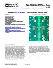
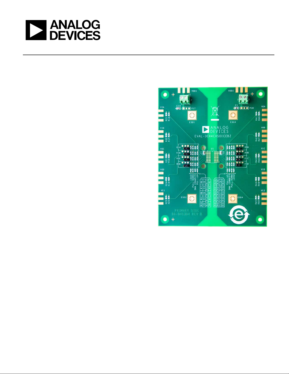
EVALUATION BOARD PHOTOGRAPH
Figure 1.
GENERAL DESCRIPTION
The EVA L -3CH4CHSOICEBZ evaluation board supports triple-
and quad-channel standard data isolators in 16-lead SOIC
packages. The evaluation board provides a JEDEC standard
16-lead SOIC_N and SOIC_W pad layout and routing appropriate
for the evaluation of supported devices. The evaluation board
provides a connection to power supplies by screw terminals and
includes optimal bypass capacitors. Signal channel routing supports
signal distribution and loopback, and provides positions for
loads referenced to the VDD1/VDD2 and GND1/GND2 planes.
Signal sources can be conducted to the board through header
pins or edge mounted SMA connectors; SMA connectors must be
ordered separately. Positions for through hole 0.2 inch headers
compatible with active probes are provided on the PCB; probe
header pins must be ordered separately.
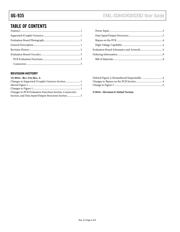
The board follows PCB design practices for 4-layer boards,
including a full power and ground plane on each side of the
isolation barrier. No other electromagnetic interference (EMI)
or noise mitigation design features are included on the board. In
cases of very high speed operation or when ultralow emissions
are required, refer to the AN-1109 application note for additional
board layout techniques.
Full specifications for the device under test (DUT) are available in
the corresponding product data sheet, which should be consulted
in conjunction with this user guide when using the evaluation
board.
14276-001
Verzeichnis