
herunterladen
EVAL-5CH6CHSOICEBZ User Guide
UG-936
One Technology Way • P. O. Box 9106 • Norwood, MA 02062-9106, U.S.A. • Tel: 781.329.4700 • Fax: 781.461.3113 • www.analog.com
Using the EVAL-5CH6CHSOICEBZ iCoupler Standard Data Isolator Evaluation Board
PLEASE SEE THE LAST PAGE FOR AN IMPORTANT
WARNING AND LEGAL TERMS AND CONDITIONS.
Rev. B | Page 1 of 8
FEATURES
Access to all data channels
Multiple connection options
Support for active probes
Provisions for cable terminations
Support for printed circuit board (PCB) edge mounted
coaxial connectors
Easy configuration
SUPPORTED iCoupler DEVICES
Sample iCoupler digital isolators must be ordered separately;
supported iCoupler devices are as follows:
ADuM150N/ADuM151N/ADuM152N
ADuM160N/ADuM161N/ADuM162N/ADuM163N
ADuM250N/ADuM251N/ADuM252N
ADuM260N/ADuM261N/ADuM262N/ADuM263N
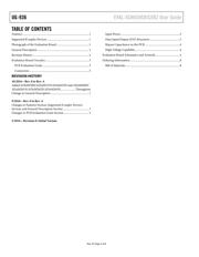
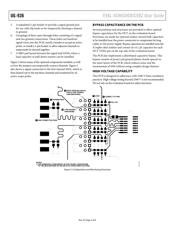
PHOTOGRAPH OF THE EVALUATION BOARD
Figure 1.
GENERAL DESCRIPTION
The EVAL-5CH6CHSOICEBZ supports 5-channel and 6-channel
iCoupler® standard data isolators in a 16-lead SOIC package. The
evaluation board provides a JEDEC standard, 16-lead SOIC_N
and SOIC_W pad layout. This layout supports signal distribution,
loopback, and loads referenced to the VDDx or GNDx planes,
as well as optimal bypass capacitance. Signal sources can be
conducted to the evaluation board through header pins or through
edge mounted SMA connectors (SMA connectors must be ordered
separately). Screw terminal blocks on the evaluation board provide
power connections.
The evaluation board includes 0.2 inch header positions for
compatibility with active probes (probe header pins must be
ordered separately).
The evaluation board follows best PCB design practices for 4-layer
boards, including a full power plane and ground plane on each
side of the isolation barrier. No other electromagnetic interference
(EMI) or noise mitigation design features are included on the
evaluation board. In cases of high speed operation, or when
ultralow emissions are required, refer to the AN-1109 Application
Note for additional evaluation board layout techniques.
14277-001
Verzeichnis