
herunterladen
ADuCM350 Hardware Reference Manual
UG-587
One Technology Way • P. O. Box 9106 • Norwood, MA 02062-9106, U.S.A. • Te l : 781.329.4700 • Fax: 781.461.3113 • www.analog.com
Scalable, Connected Precision Meter Platform with Intelligence
PLEASE SEE THE LAST PAGE FOR AN IMPORTANT
WARNING AND LEGAL TERMS AND CONDITIONS.
Rev. D | Page 1 of 459
SCOPE
This reference manual provides a detailed description of the ADuCM350 functionality and features.
Disclaimer
Information furnished by Analog Devices, Inc., is believed to be accurate and reliable. However, no responsibility is assumed by Analog
Devices for its use, nor any infringements of patents or other rights of third parties that may result from its use. Specifications subject to
change without notice. No license is granted by implication or otherwise under any patent or patent rights of Analog Devices. Trademarks and
registered trademarks are the property of their respective owners.
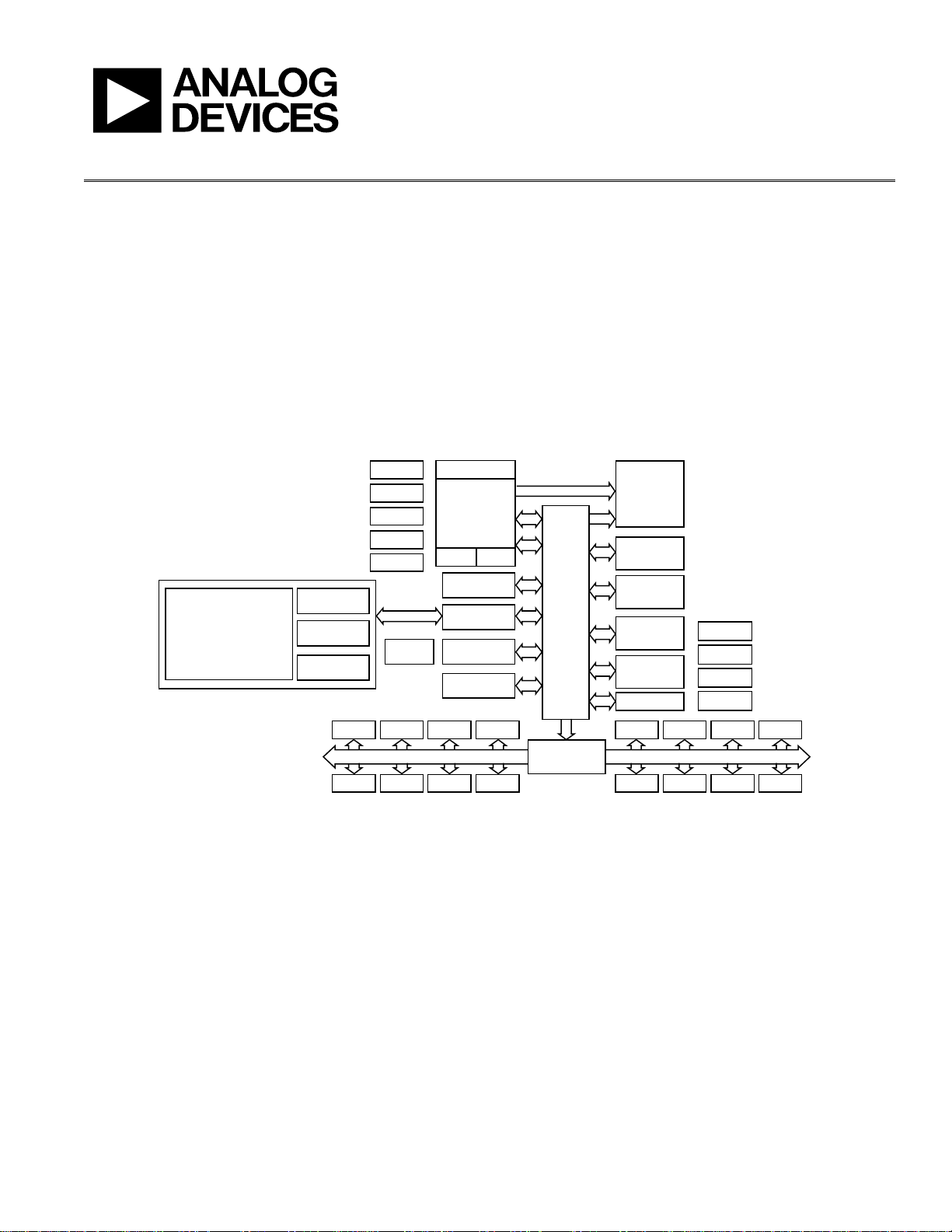
FUNCTIONAL BLOCK DIAGRAM
Figure 1. Functional Block Diagram
11714-001
AHB
‐
APB
BRIDGE
LCD
TIMER 0 TIMER 1
WDTCRC
PMU
MISC
BEEP
TIMER 2
RTC
GPIO
UART SPI0 SPI1 I
2
C
APB-0 APB-1
I
2
S
1 × 256kB
1 × 128kB
FLASH
16kB
EEPROM
SRAM1
(16kB)
PDI
PLL
LF XTAL
HF OSC
LF OSC
HF XTAL
POR
PSM
HP LDO
CapTouch
LP LDO
SPIH
AMBA
BUS
MATRIX
USB
DMA
NVIC TRACE
SW/JTAG
ARM
CORTEX-M3
SRAM0
(16kB)
AFE
CONTROLLER
DFT
SIGNAL
GENERATION
AFE
● 16-BIT PRECISION ADC
● PRECISION REFERENCE
● SWITCH MATRIX
● 12-BIT DAC
● IN AMP CONTROL LOOP
● TIA
RECEIVE
FILTERS
USB PHY
Verzeichnis