
herunterladen
One Technology Way · P.O. Box 9106 · Norwood, MA 02062-9106 · Tel: 781.329.4700 · Fax: 781.461.3113 · www.analog.com
Rev 25 Jun 2013 19:50 | Page 1
ADIS16IMU1/PCBZ Breakout Board
Wiki-Guide
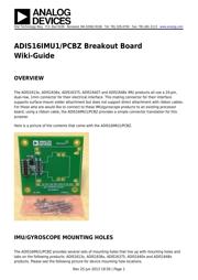
OVERVIEW
The ADIS1613x, ADIS1636x, ADIS16375, ADIS16407 and ADIS1648x IMU products all use a 24-pin,
dual-row, 1mm connector for their electrical interface. This mating connector for their interface
supports surface-mount solder attachment but does not support direct attachment with ribbon cables.
For those who are would like to connect to these IMU/gyroscope products to an existing processor
board, using a ribbon cable, the ADIS16IMU1/PCBZ provides a simple connector translation for this
purpose.
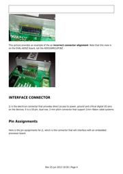
Here is a picture of the contents that come with the ADIS16IMU1/PCBZ.
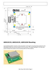
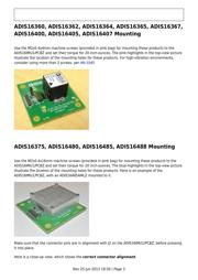
IMU/GYROSCOPE MOUNTING HOLES
The ADIS16IMU1/PCBZ provides several sets of mounting holes that line up with mounting holes and
tabs on the following products: ADIS1613x, ADIS1636x, ADIS16375, ADIS1640x and ADIS1648x
products. Please see the following picture for device mounting hole locations.
Verzeichnis