
herunterladen
EVAL-24TSSOPEBZ User Guide
UG-1036
One Technology Way • P. O. Box 9106 • Norwood, MA 02062-9106, U.S.A. • Tel: 781.329.4700 • Fax: 781.461.3113 • www.analog.com
Evaluation Board for 24-Lead TSSOP Devices in the Switches and Multiplexers Portfolio
PLEASE SEE THE LAST PAGE FOR AN IMPORTANT
WARNING AND LEGAL TERMS AND CONDITIONS.
Rev. 0 | Page 1 of 7
FEATURES
24-lead TSSOP evaluation board
Clamp allows the main device to be easily changed
Gold pin connectors allow the addition of passive
components
SMB connectors for the input/output of signals
Additional space on-board to allow for prototyping
EVALUATION KIT CONTENTS
EVAL-24TSSOPEBZ evaluation board
ONLINE RESOURCES
Documents Needed
Data sheet of the device being evaluated
EVAL-24TSSOPEBZ user guide
EQUIPMENT NEEDED
Device being evaluated
DC voltage source
Analog signal source
Method to measure voltage, such as a digital multimeter (DMM)
GENERAL DESCRIPTION
The E VA L -24TSSOPEBZ evaluation board evaluates 24-lead
TSSOP devices in the Switches and Multiplexers Portfolio,
purchased separately. A clamp is supplied with the E VA L -
24TSSOPEBZ to secure a 24-lead TSSOP device to the evaluation
board without the need for soldering, making the board reusable
for multiple devices.
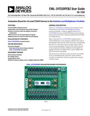
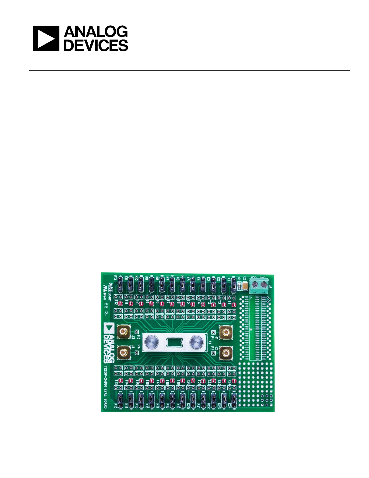
Figure 1 shows the EVA L -24TSSOPEBZ evaluation board. A
24-lead TSSOP device can be clamped or soldered to the center of
the evaluation board. Each pin of the device has a corresponding
link from K1 to K24 that can be set to either VDD or GND. A
wire screw terminal supplies VDD and GND. SMB connectors
on the evaluation board allow additional external signals to be
supplied to the device. In addition, there is space available at the
top of the board for prototyping.
Full specifications of the device under test (DUT) are available
in the corresponding product data sheet, which should be
consulted in conjunction with this user guide when using the
evaluation board.
EVAL-24TSSOPEBZ EVALUATION BOARD PHOTOGRAPH
Figure 1.
14927-001
Verzeichnis
- ・ Teilenummerierungssystem on Seite 7
- ・ Blockdiagramm on Seite 4