
herunterladen
Circuit Note
CN-0100
Circuit Designs Using Analog Devices Products
Apply these product pairings quickly and with confidence.
For more information and/or support call 1-800-AnalogD
(1-800-262-5643) or visit www.analog.com/circuit.
Devices Connected/Referenced
AD629
High Common-Mode Voltage Difference
Amplifier
AD8603
Micropower, Low Noise, CMOS Operational
Amplifier
AD7453
Pseudo-Differential, 555 kSPS, 12-Bit ADC in
8-Lead SOT-23
AD780
2.5 V/3.0 V, Ultrahigh Precision, Bandgap
Voltage Reference
Measuring −48 V High-Side Current Using the AD629 Difference Amplifier, AD8603
Op Amp, AD780 Reference, and AD7453 12-Bit ADC Single-Supply Components
Rev. 0
“Circuits from the Lab” from Analog Devices have been designed and built by Analog Devices
engineers. Standard engineering practices have been employed in the design and construction of
each circuit, and their function and performance have been tested and verified in a lab environment
at room temperature. However, you are solely responsible for testing the circuit and determining its
suitability and applicability for your use and application. Accordingly, in no event shall Analog
Devices be liable for direct, indirect, special, incidental, consequential or punitive damages due to
any cause whatsoever connected to the use of any “Circuit from the Lab”. (Continued on last page)
One Technology Way, P.O. Box 9106, Norwood, MA 02062-9106, U.S.A.
Tel: 781.329.4700
www.analog.com
Fax: 781.461.3113 ©2009 Analog Devices, Inc. All rights reserved.
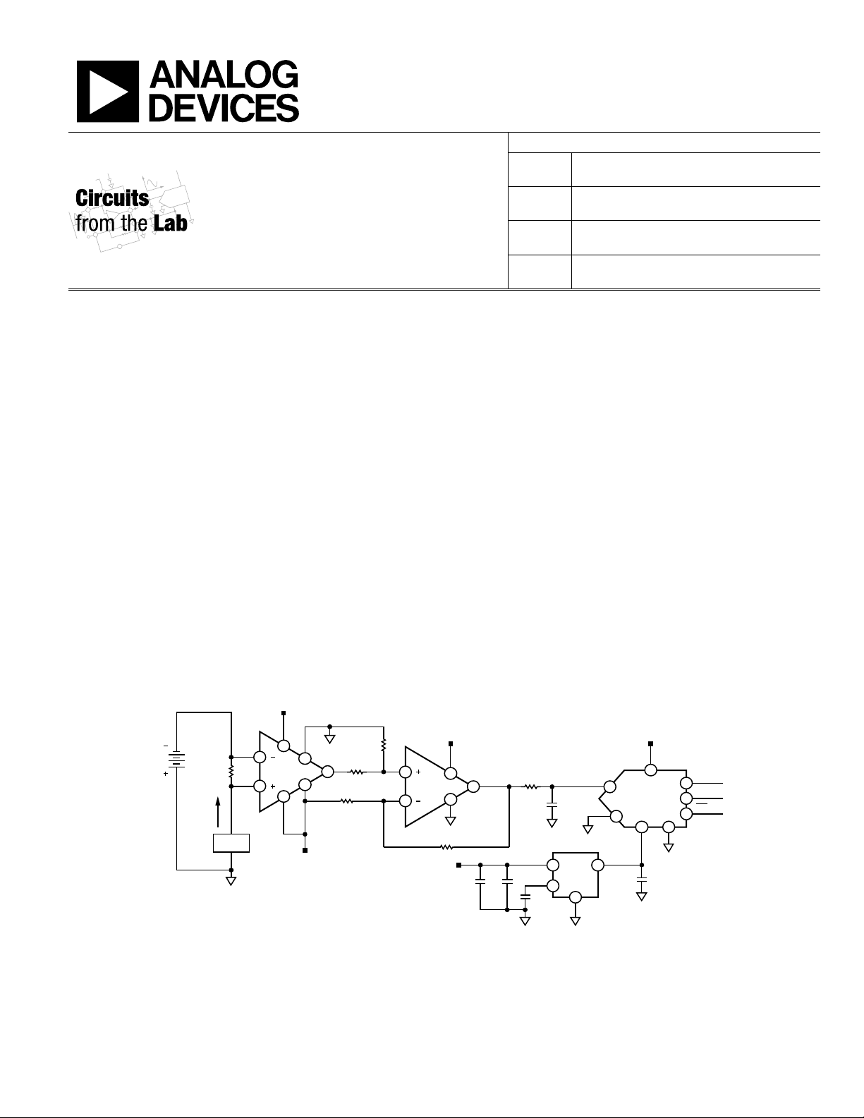
CIRCUIT FUNCTION AND BENEFITS
The −48 V power rail is widely used in wireless base stations
and telecommunication equipment. Used in network central
offices, it can vary between −48 V and −60 V. Measuring the
current at that voltage typically requires components that
operate on dual supplies, such as ±15 V. Typically, only the
front-end conditioning amplifiers that interface directly with
the −48 V rail use dual supplies. The remainder of the system
operates on single supplies. However, eliminating the negative
supply reduces complexity and cost. Using the AD629 and the
AD8603 in this circuit allows designers to measure current at
−48 V to −60 V while operating only on positive supplies.
Compared with low-side current sensing, the high-side current
sensing rejects ground noise and can detect short circuits
during operation.
CIRCUIT DESCRIPTION
This circuit uses the AD629 difference amplifier to condition
voltages beyond its supplies. The minimum and maximum
allowable input common-mode voltage is determined by the
following equations:
V
COM_MAX
= 20 × (+V
S
– 1.2) – 19 × V
REF
V
COM_MIN
= 20 × (−V
S
+ 1.2) – 19 × V
REF
When V
REF
= +5 V, +V
S
= 12 V, and −V
S
= 0 V, the AD629
common-mode input range is −71 V to +121 V. This is high
enough to cover the entire expected range of the −48 V rail. The
AD629 difference amplifier senses the differential voltage,
I
S
× R
S
, which is generated by the current flowing through the
shunt resistor. Since the AD629 has a fixed gain of 1, its output
voltage is equal to I
S
× R
S
+V
REF
.
7
1
4
5
3
6
2
5
2
4
1
3
7
62
3
4
6
8
1
5
4
3
2
R
S
100mΩ
OUTPUT
OUT
VDD
SCLK
SDATA
GNDVREF
GND
VOUT
LOAD
CS
+5V
VIN+
VIN–
1μF
AD7453
0.1μF
AD780
0.1μF
0.1μF
+5V
10μF
16V
1kΩ
V+
+5V
V–
AD8603
AD629
200kΩ
10kΩ
10kΩ
200kΩ
+IN
+IN
–IN
–IN
+5V
–V
S
+12V
+V
S
–48V
I
S
REF+REF–
08364-001
Figure 1. Circuit Used to Measure −48 V Current (Simplified Schematic)