

herunterladen

User's Guide
SLAU140A–November 2004–Revised September 2009
AD8509/8519 EVM User's Guide
Contents
1 Introduction .................................................................................................................. 1
2 Analog Interface ............................................................................................................. 1
3 Digital Interface .............................................................................................................. 2
4 Power Supplies .............................................................................................................. 3
5 EVM Operation .............................................................................................................. 4
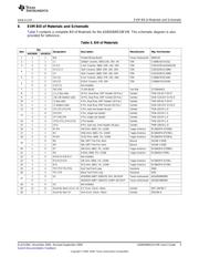
6 EVM Bill of Materials and Schematic ..................................................................................... 5
7 Related Documentation from Texas Instruments ....................................................................... 6
List of Figures
List of Tables
1 Pinout of the Analog Input Connector, J1................................................................................ 2
2 Input Range Selection ..................................................................................................... 2
3 Pinout of J3.................................................................................................................. 3
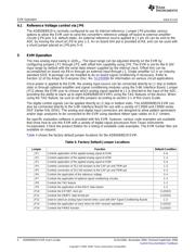
4 Factory Default Jumper Locations........................................................................................ 4
5 Bill of Materials.............................................................................................................. 5
6 EVM Compatible Device Data Sheets, Users Guides and Additional Resources.................................. 6
1 Introduction
The AD8509 and AD8519 are complete 16-bit analog-to-digital (A/D) using state-of-the-art CMOS
structures. They contain a complete 16-bit, capacitor-based, successive approximation register (SAR) A/D
with sample-and-hold, reference, clock, and a serial data interface. Data can be output using the internal
clock or can be synchronized to an external data clock. The AD8509 and AD8519 also provide an output
synchronization pulse for ease of use with standard DSP processors. The EVM is available with either the
AD8509 or AD8519 installed.
1.1 Features
• Full-Featured Evaluation Board for the AD8509 or AD8519, serial Analog to Digital Converters
• 4 V, 5 V, 10 V, ±3.3 V, ±5 V and ±10 V Analog Input Ranges
• Built in reference
• High-Speed Serial Interface
• Compatible with the 5-6K Interface Board for use with a variety of DSP Starter Kits as well as the
HPA-MCU Interface
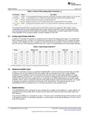
2 Analog Interface
For maximum flexibility, the AD8509/8519 EVM is designed for easy interfacing to multiple analog
sources. Samtec part numbers SSW-110-22-F-D-VS-K and TSM-110-01-T-DV-P provide a convenient
ten-pin dual row header/socket combination at J1. This header/socket provides access to the analog input
pins of the ADC. Consult Samtec at www.samtec.com or call 1-800-SAMTEC-9 for a variety of mating
connector options. Table 1 shows the pin out of the analog input connector, J1.
1
SLAU140A–November 2004–Revised September 2009 AD8509/8519 EVM User's Guide
Submit Documentation Feedback
Copyright © 2004–2009, Texas Instruments Incorporated
Verzeichnis
- ・ Blockdiagramm on Seite 5
- ・ Anwendungsbereich on Seite 9