
herunterladen
Easy to Use AD4000 Series16-/18-Bit
Precision SAR ADCs User Guide
UG-1042
One Technology Way • P. O. Box 9106 • Norwood, MA 02062-9106, U.S.A. • Te l: 781.329.4700 • Fax: 781.461.3113 • www.analog.com
Evaluation Board for the AD4000 Series 16-/18-Bit Precision SAR ADCs
PLEASE SEE THE LAST PAGE FOR AN IMPORTANT
WARNING AND LEGAL TERMS AND CONDITIONS.
Rev. B | Page 1 of 24
FEATURES
Fully featured evaluation board for 10-lead precision ADCs
Versatile analog signal conditioning circuitry
On-board reference, reference buffers, and ADC drivers
PC software for control and data analysis of time and
frequency domain
System demonstration platform-compatible (EVAL-SDP-CH1Z)
EVALUATION BOARD KIT CONTENTS
AD4000/AD4001/AD4003 evaluation board (see Table 6)
12 V wall adapter power supply
EQUIPMENT NEEDED
SDP-H1 board (EVAL-SDP-CH1Z)
Precision signal source
Cable (SMA input to evaluation board)
Standard USB A to mini-B USB cable
Band-pass filter suitable for 16-bit and 18-bit testing
(value based on signal frequency)
GENERAL DESCRIPTION
The AD4000/AD4001/AD4003 family evaluation board covers
the ease of use, 16-/18-bit, precision successive approximation
register (SAR) analog-to-digital converters (ADCs). The AD4000/
AD4001/AD4003 are low power, 16-bit/18-bit, precision SAR
ADCs that offer very high performance with throughputs up to
2 MSPS. The evaluation board is designed to demonstrate the
performance of the AD4000/AD4001/AD4003 family of ADCs
and to provide an easy to understand interface for a variety of
system applications. A full description of these products is
available in their respective data sheets, which must be consulted
when using this evaluation board.
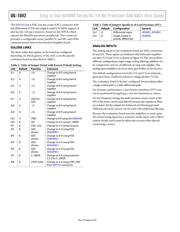
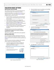
The EVAL-AD4000FMZ/EVAL-AD4001FMZ/EVAL-
AD4003FMCZ evaluation boards (see Figure 1) are ideal for use
with the Analog Devices, Inc., high speed system demonstration
platform (EVAL-SDP-CH1Z). These evaluation boards interface
to the SDP-H1 board via a 120-pin connector. SMA connectors,
JP2 and JP3, are provided for the low noise analog signal source.
On-board components include a high precision buffered band gap
5.0 V reference (the ADR4550), a reference buffer (the ADA4807-1),
a common-mode buffer (the ADA4807-1), a signal conditioning
circuit with two op amps (the ADA4807-1), and a power supply to
derive the necessary voltage levels to supply all voltage needs.
EVALUATION BOARD PHOTOGRAPH
14981-055
Figure 1.