

herunterladen
2012 Microchip Technology Inc. DS52094B
MPLAB
®
REAL ICE
™
JTAG ADAPTOR INSTRUCTION SHEET
The MPLAB REAL ICE JTAG Adaptor (AC244007) facilitates JTAG
communication between the MPLAB REAL ICE In-Circuit Emulator and
the target board. The kit contains a JTAG adaptor board, ribbon cable, and
this instruction sheet.
JTAG Support
• The JTAG adaptor board is supported on MPLAB X IDE 1.60 and
above.
• The JTAG adaptor board supports all Microchip PIC32MX devices.
• Not all debug features are available when using JTAG. View the
Debug menu to see which functions are active and which are not
available (grayed).
Switching from Standard to JTAG Communications
To switch the hardware:
1. While connected to the target using Standard Communications,
erase the target device. You may need to add “Erase Device
Memory Main Project” to a toolbar using View>Toolbars>Customize
.
2. Power down the target board.
3. Disconnect the Standard Communications cable from the target,
disconnect the USB cable from the emulator, and unplug the
Standard Driver Board from the emulator.
4. Connect one end of the ribbon cable to the connector on the JTAG
adaptor board (it should plug in only one way) and insert the JTAG
adaptor board into the emulator driver board slot.
5. Connect the other end of the ribbon cable to the connector on a
target board, such as the Microchip Explorer 16 development board.
The plug is keyed to fit only one way.
6. Connect the USB cable to the emulator and power the target board.
To set up MPLAB X IDE for JTAG operation:
1. Select File>Project Properties
. In the Project Properties dialog, click
on your desired configuration, e.g., “Conf: [default]”.
2. Click the down arrow on the “Supported Plugin Board” drop-down
box and select “JTAG Driver Board”. Click OK to accept the setup.
Switching from JTAG to Standard Communications
To switch the hardware, reverse the previous steps under “To switch the
hardware”, but do not erase the target device.
To set up MPLAB X IDE for Standard Communication operation,
repeat the previous steps under “To set up MPLAB X IDE for JTAG
operation”, except select “None” instead of “JTAG Driver Board” from the
drop-down box.
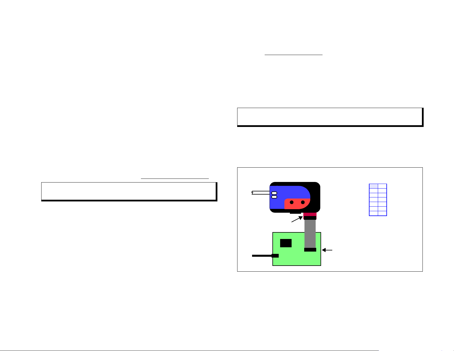
FIGURE: JTAG ADAPTOR BOARD CONNECTIONS
Documentation
For the latest information on this board, see the “Emulator Accessories”
chapter of the “MPLAB REAL ICE In-Circuit Emulator User’s Guide for
MPLAB X IDE” (DS52085) or online help file.
Note: The target device MUST BE ERASED before switching
from Standard to JTAG communications.
Note: The target device DOES NOT NEED TO BE ERASED before
switching from JTAG to Standard Communications.
Power
USB
Emulator Pod
Target Board
ACTIVE
STATUS
RESETFUNCTION
JTAG Adaptor
Ribbon Cable Connector
JTAG
PIC32MX
Board
Power
Ribbon Cable Connector
1
3
5
7
9
11
13
2
4
6
8
10
12
14
p
p
p
p
p
k
p
GND
GND
GND
GND
GND
KEY
VREF
i
i
o
i
i
od
i
TRST_N
TDI
TDO
TMS
TCK
SRST_N
DINT
MIPS - EJTAG 2.5 Connector
(Target Board)