
herunterladen
DN-26
UC3842A
LOW COST START-UP AND FAULT PROTECTION
CIRCUIT
This circuit optimizes control circuit performance to
include:
•
Low Start-up Current, Less Than 0.5 ma
•
MOSFET Compatible Undervoltage Lockout
Thresholds 16V Turn-on, 10V Turn-off
•
Programmable Restart Delay HICCUP Fault
Protection
•
Auxiliary 5V Precision Reference
•
Overvoltage/Overtemperature Protection
CIRCUIT DESCRIPTION AND OPERATION:
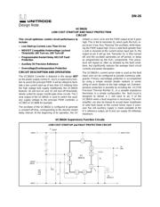
The UC3842A Controller is featured in this design
NOT
as the power supply control IC, but in a supervisory func-
tion to assist the principal PWM. It will be utilized to facili-
tate a low current start-up of less than 0.5 milliamp from
the high voltage bulk supply. Additionally, the UC3842A
features 16 volt turn-on and 10 volt turn-off thresholds,
ideally suited for power mosfet gate drive circuits. The 1
amp output of the UC3842A is used to switch the auxil-
iary supply voltage to the principal PWM controller, a
UC3825 or UC3846 for example.
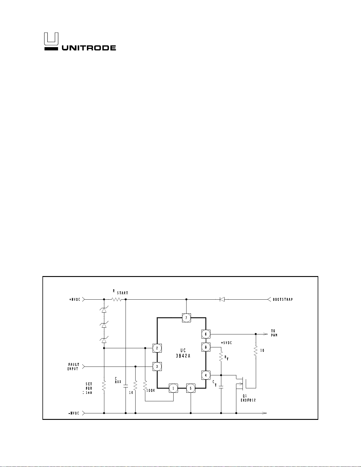
The oscillator of the UC3842A is configured to generate
a constant off time, corresponding to the desired restart
delay interval. At the beginning of its operation, the UV
initiates a clock cycle and the PWM output at pin 6 goes
high. This is fed to transistor Q
1
which pulls the R
t
/C
t
in-
put at pin 4 low, thus "freezing" the oscillator, while keep-
ing the PWM output high. Once a valid fault (greater than
1 volt) is received at the current sense input (pin 3), the
output at pin 6 will go low. Transistor Q
1
is then turned
off, and the oscillator generates an off period, or delay
as programmed by the R
t
/C
t
components. This proce-
dure will repeat as often as dictated by the fault condi-
tions, but significantly reduces the average short circuit
currents and power dissipation.
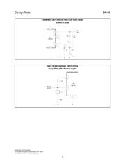
The UC3842A’s current sense node is used as the fault
input, and can be configured to provide numerous safe-
guards. Primary overvoltage protection is accomplished
by using a simple resistor divider network or series
string of zener diodes to the high voltage rail. Overtem-
perature protection is possible by including the UC3730
Precision Thermal Monitor IC, or a variable impedance
thermistor. In a simple configuration, the fault circuit is
designed to deliver a 1 volt input to pin 3 of the
UC3842A when a fault response is necessary. The error
amplifier can also be biased to accept lower amplitudes
of valid fault inputs at the current sense input. A preci-
sion five volt auxiliary supply is made available at the
IC’s reference output, pin 8 and can supply 20 milliamps
maximum.
UC3842A Supervisory Function Circuits
Design Note
LOW COST START-UP and FAULT PROTECTION CIRCUIT