
herunterladen
Application Report
SLEA098–June 2010
TVP5150AM1 Indirect Registers
.....................................................................................................................................................
1 Procedure for Accessing TVP5150AM1 Indirect Registers
The TVP5150AM1 data sheet (SLES209) describes I
2
C/PHI registers 00–FF, which are the normal way of
controlling and reading the state of the device. There are other indirect registers inside the TVP5150AM1
that are undocumented in the data sheet, but which the user may desire access to for certain applications.
These indirect registers require a four-step I
2
C transaction to read from or write to the register. Information
about these hidden indirect registers is proprietary, but may be released by TI as required.
The TVP5150AM1 indirect registers may be written to or read by an indirect method using four reserved
I
2
C/PHI registers at addresses 0x21–0x24. Indirect registers are divided into four banks, based on function
or physical location in the TVP5150AM1. The address used to access these registers is the eight
least-significant bits (LSBs) of the physical address. Each indirect register transaction reads or writes 16
bits of data, although the actual register may contain fewer defined bits. The procedures for writing to and
reading from indirect registers are detailed in the following sections. To write to an indirect register, the
TVP5150AM1 must first be unlocked, as shown in Section 1.4.
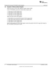
1.1 To Write to Indirect Registers
1. Write MSBs of data to I
2
C/PHI register 0x21.
2. Write LSBs of data to I
2
C/PHI register 0x22.
3. Write indirect register address (eight LSBs) to I
2
C/PHI register 0x23
4. Write the write strobe (varies, depending on bank) to I
2
C/PHI register 0x24.
1.2 To Read from Indirect Registers
1. Write indirect register address (eight LSBs) to I
2
C/PHI register 0x23.
2. Write the read strobe (varies, depending on bank) to I
2
C/PHI register 0x24.
3. Read MSBs of data from I
2
C/PHI register 0x21.
4. Read LSBs of data from I
2
C/PHI register 0x22.
Table 1. Register Banks with Read/Write Strobe Values
REGISTER BANK DESCRIPTION READ STROBE WRITE STROBE
R0–R127 General-purpose registers 01 02
0x200–0x2FF Data memory 03 04
0x300–0x3FF Digital die registers 05 06
AFE 0–9 Analog die registers 07 08
1.3 Example 1: Read from Indirect Register
Read value for HSYN_Start, digital die register address 0x34D.
1. Write 0x4D to I
2
C/PHI register 0x23
2. Write 0x05 to I
2
C/PHI register 0x24.
3. Read MSBs of 10-bit HSYN_Start from I
2
C/PHI register 0x21.
4. Read LSBs of 10-bit HSYN_Start from I
2
C/PHI register 0x22.
1
SLEA098–June 2010 TVP5150AM1 Indirect Registers
Copyright © 2010, Texas Instruments Incorporated