

herunterladen
Measurement Techniques
www.vishay.com
Vishay Semiconductors
Rev. 1.4, 31-Jul-12
1
Document Number: 80085
For technical questions, contact: emittertechsupport@vishay.com
THIS DOCUMENT IS SUBJECT TO CHANGE WITHOUT NOTICE. THE PRODUCTS DESCRIBED HEREIN AND THIS DOCUMENT
ARE SUBJECT TO SPECIFIC DISCLAIMERS, SET FORTH AT www.vishay.com/doc?91000
Measurement Techniques
INTRODUCTION
The characteristics of optoelectronics devices given in
datasheets are verified either by 100 % production tests
followed by statistic evaluation or by sample tests on typical
specimens. These tests can be divided into following
categories:
• Dark measurements
• Light measurements
• Measurements of switching characteristics, cut-off
frequency and capacitance
• Angular distribution measurements
• Spectral distribution measurements
• Thermal measurements
Dark and light measurements limits are 100 %
measurements. All other values are typical. The basic
circuits used for these measurements are shown in the
following sections. The circuits may be modified slightly to
accommodate special measurement requirements.
Most of the test circuits may be simplified by use of a source
measure unit (SMU), which allows either to source voltage
and measure current or to source current and measure
voltage.
DARK AND LIGHT MEASUREMENTS
EMITTER DEVICES
IR Diodes
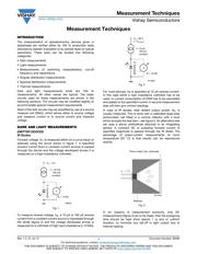
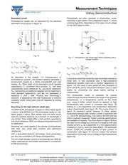
Forward voltage, V
F
, is measured either on a curve tracer or
statically using the circuit shown in figure 1. A specified
forward current (from a constant current source) is passed
through the device and the voltage developed across it is
measured on a high-impedance voltmeter.
Fig. 1
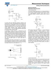
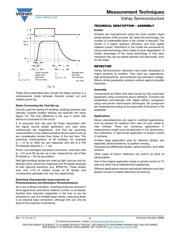
To measure reverse voltage, V
R
, a 10 μA or 100 μA reverse
current from a constant current source is impressed through
the diode (figure 2) and the voltage developed across is
measured on a voltmeter of high input impedance (≥ 10 MΩ).
Fig. 2
For most devices, V
R
is specified at 10 μA reverse current.
In this case either a high impedance voltmeter has to be
used, or current consumption of DVM has to be calculated
and added to the specified current. A second measurement
step will then give correct readings.
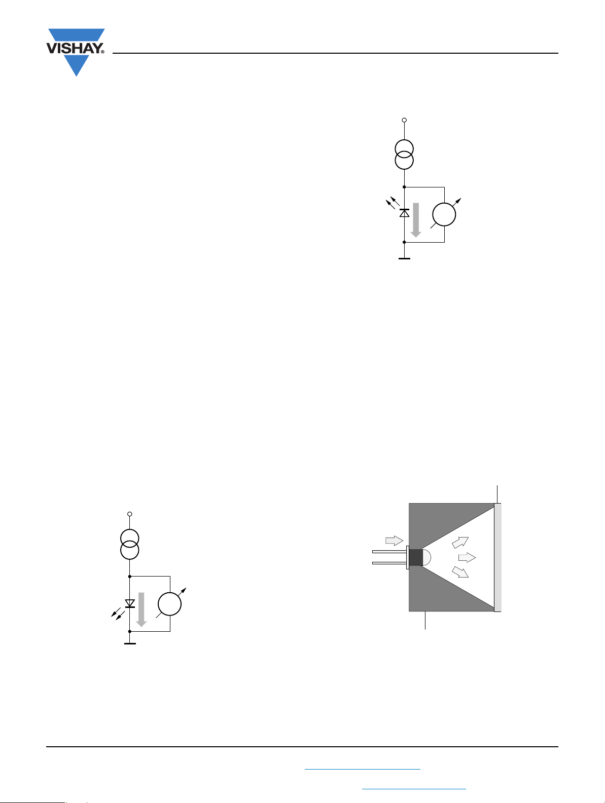
In case of IR diodes, total radiant output power, Φ
e
, is
usually measured. This is done with a calibrated large-area
photovoltaic cell fitted in a conical reflector with a bore
which accepts the test item - see figure 3. An alternative test
set uses a silicon photodiode attached to an integrating
sphere. A constant DC or pulsating forward current of
specified magnitude is passed through the IR diode. The
advantage of pulse-current measurements at room
temperature (25 °C) is that results can be reproduced
exactly.
Fig. 3
If, for reasons of measurement economy, only DC
measurements (figure 4) are to be made, then the energizing
time should be kept short (below 1 s) and of uniform
duration, to minimize any fall-off in light output due to
internal heating.
V
S
= 5 V
R
i
> 10 kΩ
V
V
F
I = 50 mA
100 mA
constant
948205
V
S
= 80 V
( > V
R max.
)
R
i
> 10 MΩ
V
V
R
I = 10 µA
100 µA
constant
94 8206
I
F
Photo Voltaic Cell, Calibrated
Reflector
94 8155