
herunterladen

Application Report
SLVA485–October 2011
Choosing an Appropriate Pull-up/Pull-down Resistor for
Open Drain Outputs
Ben Hopf ....................................................................................... PMP-DC/DC Low-Power Converters
ABSTRACT
Many ICs contain digital output pins to indicate certain statuses to the rest of the system. These outputs
fall into two categories: open drain (open collector for bipolar outputs) or push-pull (also known as totem
pole). Open drain outputs are commonly utilized because they offer several advantages when compared
to push-pull outputs. Unlike push-pull outputs, several open drain outputs from different devices can be
connected directly together to create an OR function. Also, open drain outputs provide more flexibility to a
designer as they can be pulled-up to any voltage found in the system, which can be useful when they
serve as inputs to a processor which might require a lower voltage level than the push-pull output would
give. Examples of open drain outputs commonly found on ICs include Power Good (PG) and Low Battery
(LBO) on switching regulators, reset and Power Fail (PFO) on supply voltage supervisors (SVS), and Low
Battery, Power Fail, and reset on power management units. All open drain outputs require the use of an
external pull-up or pull-down resistor to keep the digital output in a defined logic state. This application
report discusses when to use a pull-up or pull-down resistor, the factors that should be considered when
selecting a pull-up or pull-down resistor, and how to calculate a valid range for the value of the resistor.
Contents
1 Introduction .................................................................................................................. 2
2 Calculating the Pull-up Resistor Range .................................................................................. 2
3 Calculating the Range of R
Pull-up
for the TPS62067 ..................................................................... 4
4 Calculating the Pull-down Resistor Range .............................................................................. 5
5 Calculating the Range of R
Pull-down
for the TL7759 ....................................................................... 6
6 Other Selection Considerations ........................................................................................... 7
7 Conclusion ................................................................................................................... 8
List of Figures
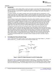
1 Typical PG Output Equivalent Circuit (PG Floating High) ............................................................. 2
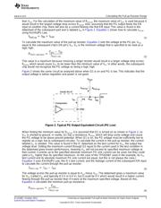
2 Typical PG Output Equivalent Circuit (PG Low) ........................................................................ 3
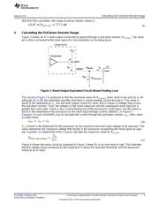
3 Reset Output Equivalent Circuit (Reset Floating Low)................................................................. 5
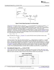
4 Reset Output Equivalent Circuit (Reset High)........................................................................... 6
List of Tables
1 PG Output IC ............................................................................................................... 4
2 EN Input IC .................................................................................................................. 4
3 Reset Output IC ............................................................................................................ 6
4 Typical Reset Input IC ..................................................................................................... 7
1
SLVA485–October 2011 Choosing an Appropriate Pull-up/Pull-down Resistor for Open Drain Outputs
Submit Documentation Feedback
Copyright © 2011, Texas Instruments Incorporated