
herunterladen
2002 Microchip Technology Inc. DS00761B-page 1
M
AN761
INTRODUCTION
Battery-operated equipment (most notably cell phones
and notebook computers) have created a strong
demand for linear regulators in small packages. While
such packages save space, they also have poor heat
transfer characteristics. To minimize power dissipation,
these regulators are designed to work with very low
input/output voltage differentials, hence the name “low
dropout regulators” or LDOs.
LDOs specify maximum output current and input
voltage limits, but blindly operating the LDO within
these limits will surely result in exceeding the maximum
power dissipation capability.
DISSIPATING HEAT
Like other power devices, LDOs dissipate heat
generated in the die by convection at rates determined
by the thermal resistances in the system. Heat
dissipation by convection is determined by the thermal
resistance from the junction to ambient (Θ
JA
). Typically,
heat sinks and/or forced air techniques may be used to
decrease Θ
JA
, but not without impacting system size
and cost.
In addition to convection, heat is also removed from the
LDO by conduction (i.e., through any portion of the
package that is in contact with the circuit board). In this
case, increasing copper trace size and improving
thermal interface (using thermal grease or films)
significantly improves conduction cooling efficiency.
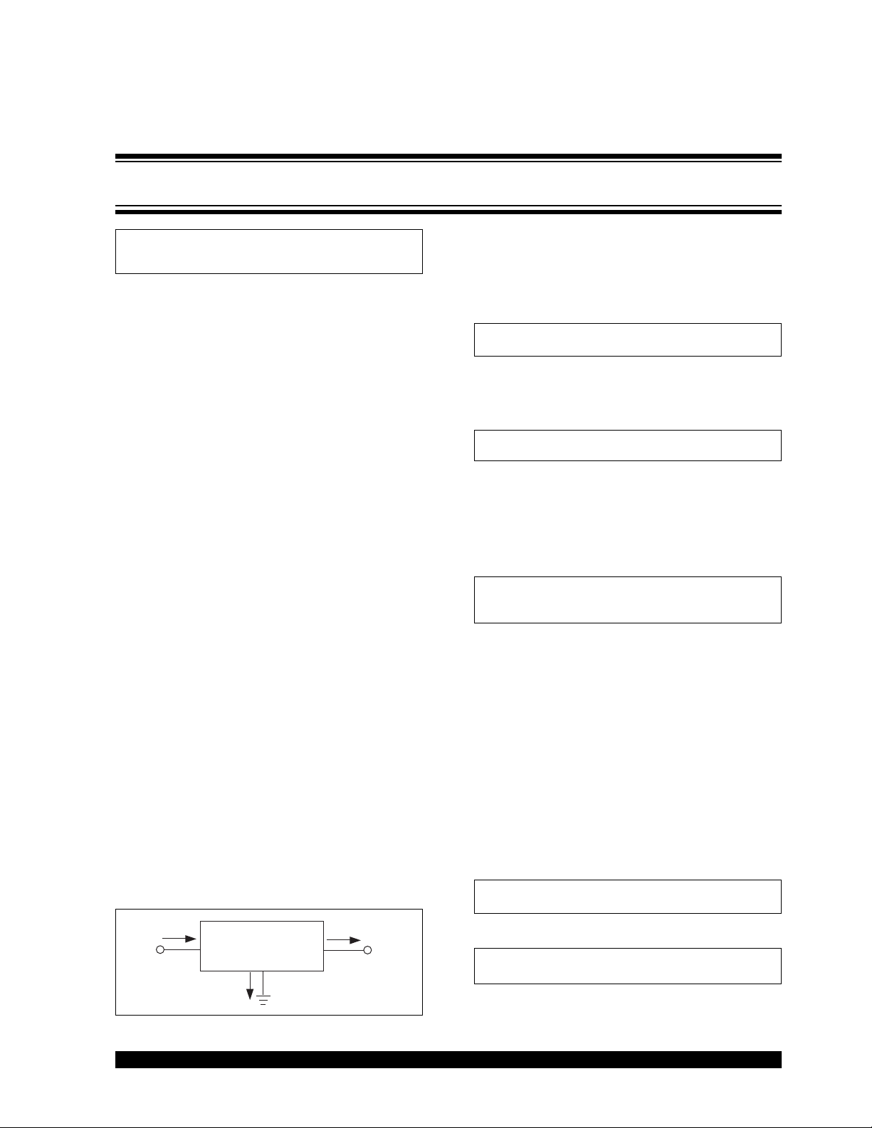
LDO POWER DISSIPATION
Determining the power dissipated by an LDO involves
a straight forward calculation. The current entering the
LDO can only go two places: through the pass device
to the output (I
OUT
); or through the internal bias circuitry
to ground (I
GND
). See Figure 1.
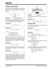
FIGURE 1: LDO Power Dissipation
The conservation of power, states that power in must
equal power out. Consequently, input power is equal to
the power delivered to the load plus the power
dissipated in the LDO, (Equation 1):
EQUATION 1:
The power dissipation of the LDO is expressed in
Equation 2:
EQUATION 2:
When calculating power dissipation, it is critical that
worst case conditions be used. This means maximum
V
IN
, I
LOAD
, and I
GND
, and minimum V
OUT
values.
Equation 2 is more accurately written as Equation 3.
EQUATION 3:
EXAMPLE 1:
The TC1264VAB-3.0 (0.8A LDO in a TO-220-3
package) is being used to regulate a 5V supply down to
3.0V. The 5V supply is specified to have an output
tolerance of ±5%. The maximum load on the 3.0V
supply is 0.7A. The system operating temperature
range is from 20°C to 70°C.
Given: Maximum supply current = 130 µA
V
INMAX
= (5V x 1.05) = 5.25V
V
OUTMIN
= 2.93V
Therefore, (Equation 4 and Equation 5).
EQUATION 4:
EQUATION 5:
Author: Paul Paglia,
Microchip Technology Inc.
V
OU
T
I
GND
I
OUT
OUT
LDO
IN
V
IN
I
IN
P
IN
= P
OUT
+ P
LDO
P
D
= (V
IN
– V
OUT
) x I
LOAD
+ V
IN
x I
GND
P
DMAX
= (V
INMAX
– V
OUTMIN
) x I
LOADMAX
+
V
INMAX
x I
GNDMAX
P
DMAX
= (5.25V – 2.93V) x 0.7A + 5.25V x 130 µA
P
DMAX
= 1.62W
LDO Thermal Considerations