
herunterladen
1/28
AN594
Application note
October 2008 Rev 2
Direct LCD drive with
ST621xx and ST626xx
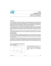
Introduction
This note describesatechnique for drivingaLiquid Crystal Display (LCD) withastandard ST62
microcontroller (MCU), without any dedicated LCD driver. This technique offersadisplay capa-
bility for applications which require a small display atalow cost together with the versatile ca-
pabilities of the standard ST62xx MCU. Higher display requirements are easily handled by
dedicated members of the ST62 MCU family, for example the ST6240B.
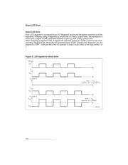
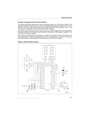
The first part of this note describes the typical waveforms required to drive an LCD correctly
withamultiplexing rate of1or2(duplex). The following parts present two solutions based on
standard ST62 MCUs driving directly the LCD. The first is based on an ST6215 without using
software interrupts and the second on an ST6265 where the LCD is controlled by timer inter-
rupts.
In both examples the program size, the CPU time occupation due to the LCD drive and the number
of surrounding components are minimized. Consequently many additional tasks can be added to
the MCU program.
LCD requirements
Withazero Root Mean Square (RMS) voltage applied to it, an LCD is practically transparent.
The LCD contrast, which makes the segments turn dark or opaque and thus “on”, is caused by
the difference between the RMS LCD voltage applied and the LCD threshold voltage, specific
to each LCD type.
The applied LCD voltage must alternate to giveazero DC value in order to ensurealong life
time of
the LCD. The higher the multiplexing rate is, the lower the contrast, also the period of
the signal has to be short enough to avoid visible flickering of the LCD display. The LCD volt-
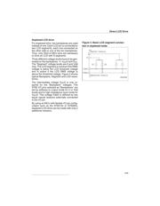
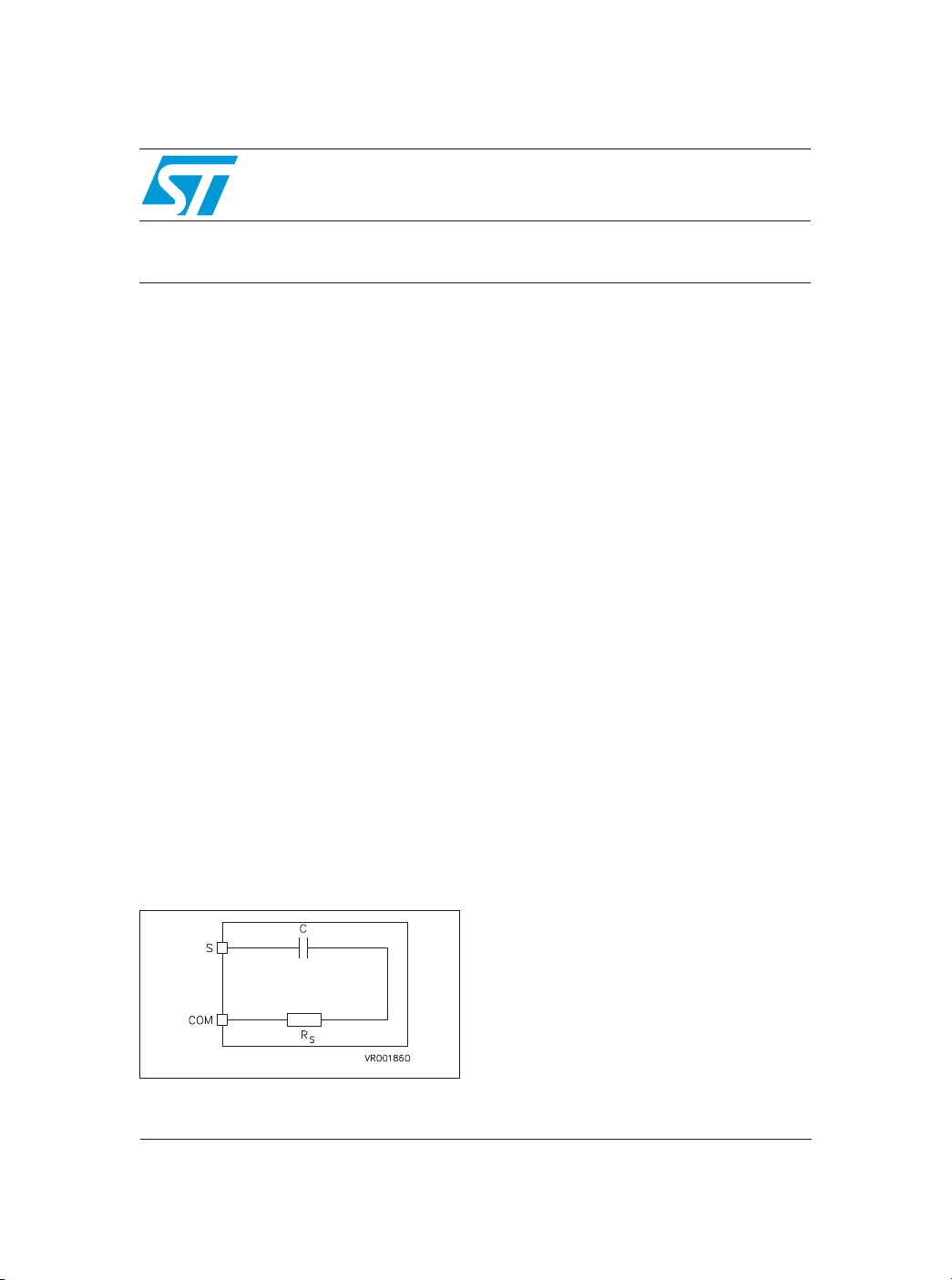
age for each segment equals to the difference between theSand COM voltages (see Figure
1).
Figure 1. Equivalent electrical schematic
of an LCD segment
-
DC value should never be more than
100mV. Else time life can be shorten.
-
Frequency range is 30-2000Hz typically.
Less, it flickers; more, consumption
grows.
Verzeichnis
- ・ Blockdiagramm on Seite 6
- ・ Anwendungsbereich on Seite 18 Seite 28