
herunterladen
This is information on a product in full production.
September 2013 Doc ID 16100 Rev 7 1/103
1
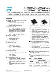
SPC560P34L1, SPC560P34L3
SPC560P40L1, SPC560P40L3
32-bit Power Architecture
®
based MCU with 320 KB Flash memory
and 20 KB RAM for automotive chassis and safety applications
Datasheet − production data
Features
■
Up to 64 MHz, single issue, 32-bit CPU core
complex (e200z0h)
– Compliant with Power Architecture
®
embedded category
– Variable Length Encoding (VLE)
■
Memory organization
– Up to 256 KB on-chip code flash memory
with ECC and erase/program controller
– Additional 64 (4 × 16) KB on-chip data
flash memory with ECC for EEPROM
emulation
– Up to 20 KB on-chip SRAM with ECC
■
Fail-safe protection
– Programmable watchdog timer
– Non-maskable interrupt
– Fault collection unit
■
Nexus Class 1 interface
■
Interrupts and events
– 16-channel eDMA controller
– 16 priority level controller
– Up to 25 external interrupts
– PIT implements four 32-bit timers
– 120 interrupts are routed via INTC
■
General purpose I/Os
– Individually programmable as input, output
or special function
– 37 on LQFP64
– 64 on LQFP100
■
1 general purpose eTimer unit
– 6 timers each with up/down capabilities
– 16-bit resolution, cascadable counters
– Quadrature decode with rotation direction
flag
– Double buffer input capture and output
compare
■
Communications interfaces
– 2 LINFlex channels (1× Master/Slave, 1×
Master only)
– Up to 3 DSPI channels with automatic chip
select generation (up to 8/4/4 chip selects)
– Up to 2 FlexCAN interface (2.0B Active)
with 32 message buffers
– 1 safety port based on FlexCAN with 32
message buffers and up to 8 Mbit/s at
64 MHz capability usable as second CAN
when not used as safety port
■
One 10-bit analog-to-digital converter (ADC)
– Up to 16 input channels (16 on LQFP100 /
12 on LQFP64)
– Conversion time < 1 µs including sampling
time at full precision
– Programmable Cross Triggering Unit (CTU)
– 4 analog watchdogs with interrupt
capability
■
On-chip CAN/UART bootstrap loader with Boot
Assist Module (BAM)
■
1 FlexPWM unit: 8 complementary or
independent outputs with ADC synchronization
signals
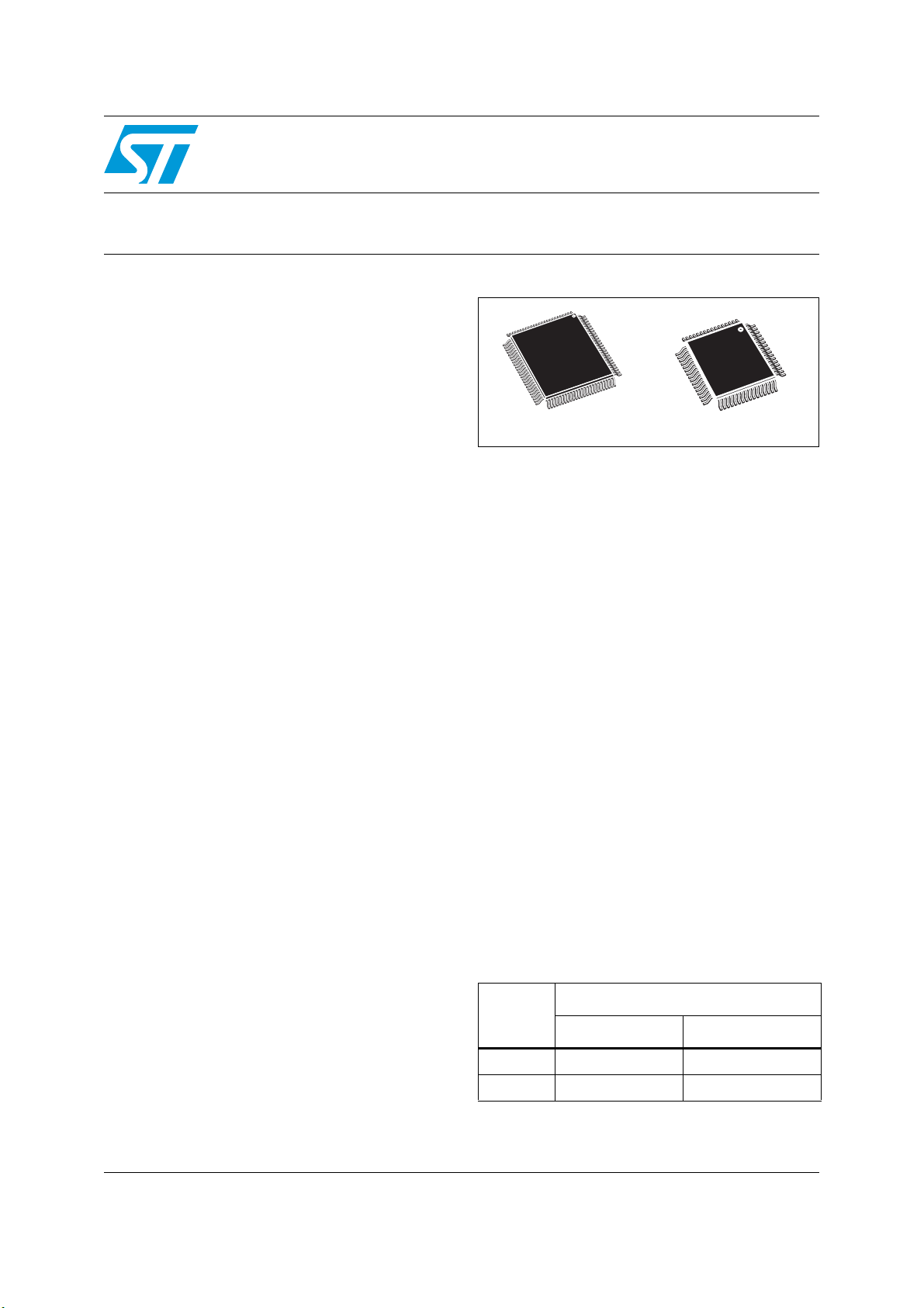
Table 1. Device summary
Package
Code flash memory
192 KB 256 KB
LQFP100 SPC560P34L3 SPC560P40L3
LQFP64 SPC560P34L1 SPC560P40L1
LQFP64 (10 x 10 x 1.4 mm)
LQFP100 (14 x 14 x 1.4 mm)
www.st.com
Verzeichnis
- ・ Konfiguration des Pinbelegungsdiagramms on Seite 33
- ・ Abmessungen des Paketumrisses on Seite 29 Seite 30 Seite 31 Seite 32 Seite 33
- ・ Teilenummerierungssystem on Seite 96 Seite 97
- ・ Blockdiagramm on Seite 9 Seite 10
- ・ Technische Daten on Seite 35 Seite 46 Seite 47 Seite 103
- ・ Anwendungsbereich on Seite 53 Seite 103
- ・ Elektrische Spezifikation on Seite 45 Seite 46 Seite 47 Seite 48 Seite 49