
herunterladen
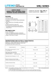
SMCJ SERIES
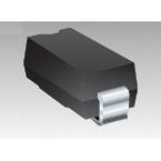
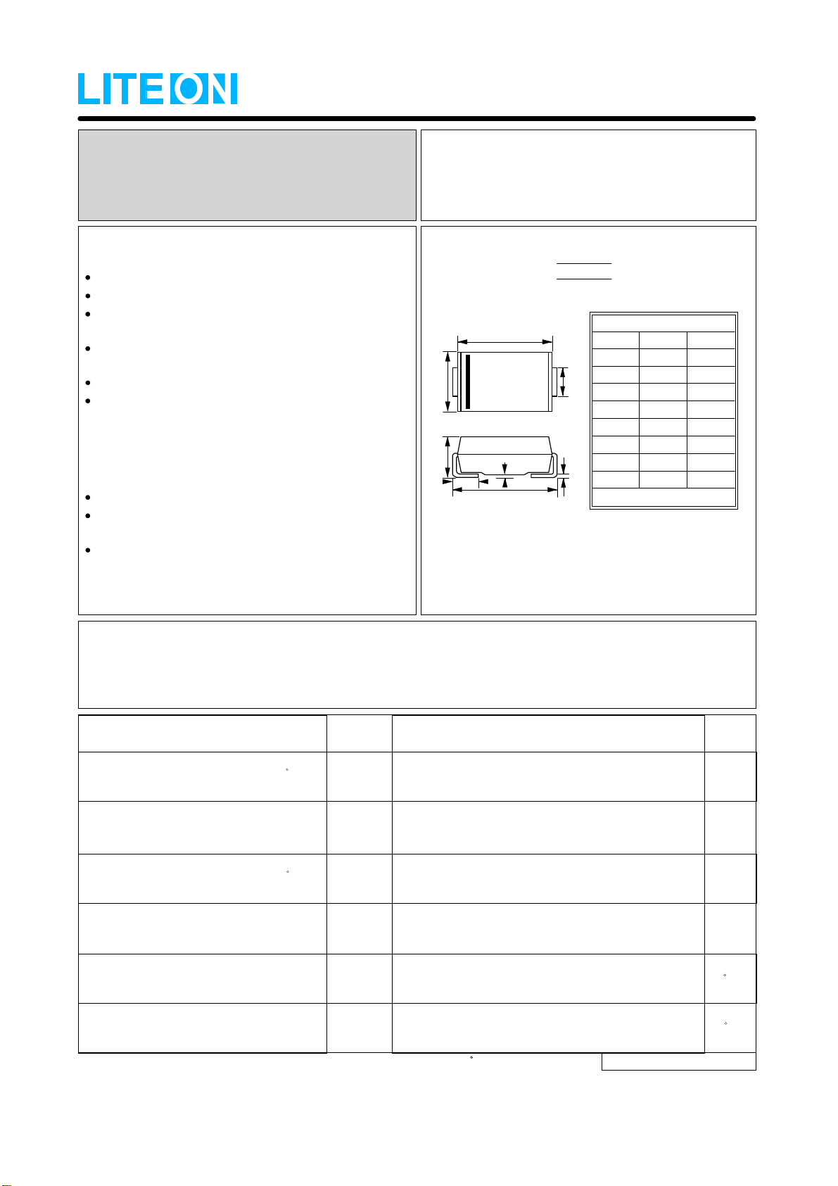
SMC
All Dimensions in millimeter
SMC
DIM. MIN. MAX.
A
C
D
E
F
G
H
B
6.60 7.11
6.22 5.59
2.92
3.18
0.31 0.15
7.75 8.13
0.05 0.20
2.01 2.62
0.76 1.52
C
H
E
F
G
D
B
A
FEATURES
Rating to 200V VBR
For surface mounted applications
Reliable low cost construction utilizing molded plastic
technique
Plastic material has UL flammability classification
94V-O
Typical IR less than 1uA above 10V
Fast response time: typically less than 1.0ps for
Uni-direction,less than 5.0ns for Bi-direction,form 0
Volts to BV min
MECHANICAL DATA
Case : Molded plastic
Polarity : by cathode band denotes uni-directional
device none cathode band denotes bi-directional device
Weight : 0.007 ounces, 0.21 gram
T
J
Operating Temperature Range
-55 to +150
T
STG
Storage Temperature Range
-55 to +175
C
I
FSM
Peak Forward Surge Current 8.3ms
single half sine-wave super imposed
on rated load (Note 3)
200
AMPS.
UNIT
P
M(AV)
5.0
WATTS
Steady State Power Dissipation at T
L
=75 C
P
PK
WATTS
PEAK POWER DISSIPATION AT T
A
= 25 C,
T
P
= 1ms (Note 1,2)
SYMBOLS VALUE
Minimum 1500
C
CHARACTERISTICS
(JEDEC METHOD)
SURFACE MOUNT
UNIDIRECTIONAL AND BIDIRECTIONAL
TRANSIENT VOLTAGE SUPPRESSORS
STAND-OFF VOLTAGE -
5.0
to
170
Volts
POWER DISSIPATION -
1500
WATTS
Maximum Instantaneous forward voltage
at 100A for unidirectional devices only (Note 3)
V
F
SEE NOTE 4 Volts
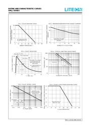
NOTES : 1. Non-repetitive current pulse, per fig. 3 and derated above T
A
= 25 C per fig.1.
2. Thermal Resistance junction to Lead
3. 8.3ms single half-sine wave duty cycle= 4 pulses maximum per minute (unidirectional units only).
4. V
F
= 3.5V on SMCJ5.0 thru SMCJ90A devices and V
F
= 5.0V on SMCJ100 thru SMCJ170A devices.
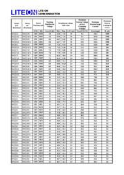
MAXIMUM RATINGS AND ELECTRICAL CHARACTERISTICS
Ratings at 25
℃
ambient temperature unless otherwise specified.
Single phase, half wave, 60Hz, resistive or inductive load.
For capacitive load, derate current by 20%
SEMICONDUCTOR
LITE-ON
REV. 2, 01-Dec-2000, KSIC02
Verzeichnis